2 x 12 Pergola room Installation and Operating Instructions – YM11635X Retractable Sunshade Sold Separately Yardistry – North America Toll Free Customer Support: 1.888.509.4382 info@yardistrystructures.com www.yardistrystructures.com Yardistry / Selwood Products – Europe Customer Support: +44 1284 852569 parts@selwoodproducts.com www.selwoodproducts.com 3.05 m (10’) 3.66 m (12’) 1 12’ (3.66 m) 10’ (3.05 m) Revised 12/22/2014 HEIGHT: 8’2” or 2.49m support@yardistrystructures.
Important Safety Notice! Yardistry components are intended for privacy, decorative and ornamental use only. Product is NOT INTENDED for the following: • A safety barrier to prevent unsupervised access to pools, hot tubs, spas or ponds. • As load bearing support for a building, structure, heavy objects or swings. • Used in structures that trap wind, rain or snow that would create extra load on the product. Permanent structures may require a building permit.
Limited Warranty Yardistry warrants that this product is free from defect in materials and workmanship for a period of one year from the original date of purchase. In addition, all lumber is warranted for 5 years against rot and decay. This warranty applies to the original owner and registrant and is non-transferable. Regular maintenance is required to assure the integrity of your product and is a requirement of the warranty. This warranty does not cover any inspection cost.
Instructions for Proper Maintenance Your Yardistry structure is designed and constructed of quality materials. As with all outdoor products it will weather and wear. To maximize the enjoyment, safety and life of your structure it is important that you, the owner, properly maintain it. HARDWARE: • • • Check metal parts for rust. If found, sand and repaint using a non-lead paint complying with 16 CFR 1303.
Permanent Installation Examples Note: It is critically important you start with square, solid and level footings, concrete pad or deck to attach your Pergola Room. We supply Room L-Mounts with this structure which gives you the flexibility to permanently install your structure to a pre-existing or new wood or concrete surface. • The hardware to attach the Room L-Mount to the structure is included.
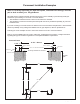
Permanent Installation Examples cont. Concrete Patio (min. 10’ 2” x 10’ 2”) with 12” clearance on all sides #10 x 1-1/4” Pan Screws Included Anchoring Hardware not included Wood Deck (min. 10’ 2” x 10’ 2”) with 12” clearance on all sides #10 x 1-1/4” Pan Screws Included Anchoring Hardware not included Post #10 x 1-1/4” Pan Screw Room L-Mount 6 support@yardistrystructures.
support@yardistrystructures.
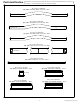
are approximate and are shown to assist in the identification of parts for Part Identification ( Dimensions ) assembly. Actual dimensions may be smaller or larger. 38.1 x 38.1 x 409.6mm 32pc. (185) - Horizontal Insert 2 x 2 x 16-1/8" - Box 2 Y50119-185 38.1 x 38.1 x 574.7mm 64pc. - X Insert 2 x 2 x 22-5/8" - Box 3 Y50119-183 38.1 x 63.5 x 850.9mm 9pc. (062)- Trellis End 33-1/2" 2 x 3 x 33-1/2" - Box 1 Y50119-062 38.1 x 63.5 x 2806.7mm 9pc.
are approximate and are shown to assist in the identification of parts for Part Identification ( Dimensions ) assembly. Actual dimensions may be smaller or larger. 38.1 x 241.3 x 3048.0mm 2pc. (080) - Arch Beam Offset 2 x 6 x120" - Box 1 Y50119-080 38.1 x 241.3 x 3048.0mm 2pc. (195) - Arch Beam Front 2 x 6 x120" - Box 1 Y50119-195 38.1 x 241.3 x 3048.0mm 1pc. (079) - Arch Beam Center 2 x 6 x120" - Box 1 Y50119-079 38.1 x 139.7 x 2070.1mm 2pc.
Hardware Identification ( Dimensions are approximate and are shown to assist in the identification of parts for assembly. Actual dimensions may be smaller or larger. 144pc. - Wood Screw #8 x 3" - (Y06420-530) 48pc. - Wood Screw #8 x 2-1/2" - (Y06420-522) 50pc. - Pan Screw #10 x 1-1/4" - (Y06420-911) 9pc. - Wafer Bolt 1/4 x 2" - (Y07420-220) ) 98pc. - Wood Screw #10 x 4" - (Y06420-940) 96pc. - Trim Screw #6 x 30mm - (Y06420-910) 8pc. - Wafer Bolt 1/4 x 4-1/4" - (Y07420-241) 16pc.
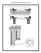
Step 1: Inventory Parts - Read This Before Starting Assembly STOP A. STOP STOP STOP his is the time for you to inventory all your hardware, wood and accessories, T referencing the parts identification sheets. This will assist you with your assembly. • Each step indicates which bolts and/or screws you will need for assembly, as well as any flat washers, lock washers, t-nuts or lock nuts. B.
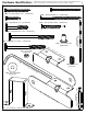
Step 2: Assemble “X” Inserts A: Place one X Insert Pin into one X Insert, then attach a second X Insert to form a complete Insert. Make sure the pieces are tight to each other. B: Repeat Step A to make 32 complete Inserts. Fig. 2.1 X Insert Pin X Insert Wood Parts Hardware 64 x X Insert 38.1 x 38.1 x 574.7 mm (2 x 2 x 22-5/8”) 32 x X Insert Pin 12 support@yardistrystructures.
Step 3: Assemble 8 Panels Part 1 (024) Engineered Panel Post Top Fig. 3.1 Note: You will be assembling 8 Panel Post Assemblies in total in Step 3. A: Lay one (024) Engineered Panel Post and one (025) Engineered Panel Corner Post on edge so the grooved sides face each other, on a level surface. (025) Engineered Panel Corner Post B: Place one (191) Bottom Brace Insert in between the posts tight to the bottom ledge and attach with two #8 x 3” Wood Screws as shown in fig. 3.1.
Step 3: Assemble 8 Panels Part 2 Fig. 3.2 Fig. 3.3 C: Slide one complete Insert in from the top of the panels and down to the (185) Horizontal Insert. (fig. 3.2) (189) Cross Brace Insert #8 x 3” Wood Screws x 5 D: Slide one (185) Horizontal Insert to the top of the complete Insert. (fig. 3.2) Attach with two #8 x 3” Wood Screws. (024) Engineered Panel Post Note: Be sure to maintain 16” measurement between each (185) Horizontal Insert. (fig 3.
Step 4: Attach Panel Posts to Corner Posts Part 1 Note: Only pre-drill one post per assembly A: On Engineered Panel Corner Post, per assembly, pre-drill two holes from the inside, at the places shown in fig. 4.1 and 4.2. Pre-drill in the centre of the panel and on a slight angle. (024) Engineered Panel Post (025) Engineered Panel Corner Post Fig. 4.1 Fig. 4.2 Pre-drill on a slight angle 15 support@yardistrystructures.
Step 4: Attach Panel Posts to Corner Posts Part 2 Fig. 4.3 B: Through the pre-drilled holes attach two Panel Posts assemblies to one (190) Corner Post with one #10 x 4” Wood Screw per Panel Post Assembly at bottom and six #8 x 2-1/2” Wood Screws along post as shown in fig. 4.3. Start at the bottom and work up. #8 x 2-1/2” Wood Screws (190) Corner Post #8 x 2-1/2” Wood Screws Complete this step for all four Corner Posts.
Step 5: Attach L - Mount Brackets A: Pre-drill with a 1/8” drill bit and attach two L Mounts (one L Mount Right and one L Mount Left) flush to the inside edge, at the bottom of each Panel Post with two #10 x 1-1/4” Pan Screw per L Mount as shown in fig. 5.1, 5.2 and 5.3. Fig. 5.1 Fig. 5.3 L Mount Right Note orientation of tabs. #10 x 1-1/4” x 2 per L Mount Pan Screw L Mount Right Note: Flush to the inside edge. L Mount Left Fig. 5.
Step 6: Attach Plinths to Corner Post Assembly Part 1 A: Place one (034) Short Plinth B Assembly with one (035) Short Plinth A Assembly tight to each other and attach using two #6 x 30 mm Trim Screw at the opposite corners per Plinth. (Fig. 6.1 and 6.2) Note: Plinths will be attached to four corners. Fig. 6.1 Plinths rest on top of the L Mounts Flush to corners Fig. 6.
Step 6: Attach Plinths to Corner Post Assembly Part 2 B: On the outside of the corner post assembly, place two (033) Long Plinth Assembly tight against eachother using 2 #6 x 30 mm Trim Screws per Plinth. Be sure they are flush and tight. (Fig. 6.3 and 6.4) Fig. 6.3 Fig. 6.4 (033) Long Plinth Assembly #6 x 30 mm Trim Screw x 2 per board Flush Wood Parts Hardware 8 x (033) Long Plinth Assembly 34.9 x 152.4 x 598.5 mm 16 x #6 x 30 mm Trim Screw 19 support@yardistrystructures.
Step 6: Attach Plinths to Corner Post Assembly Part 3 C: Place one (032) End Plinth Assembly onto each Corner Post Assembly. Line them up with previously placed Plinths. Make sure they are flush and tight to each other and then fasten with two #6 x 30 mm Trim Screw per end. (Fig. 6.5 and 6.6) Fig. 6.5 #6 x 30 mm Trim Screw Fig. 6.6 (032) End Plinth Assembly (032) End Plinth Assembly Flush #6 x 30 mm Trim Screw Note: Loosen screws as necessary to align all edges.
Step 6: Attach Plinths to Corner Post Assembly Part 4 Note: Make sure all plinths are lined up, flush and level before installing remaining screws. D: After the End Plinths have been placed, go back and install the two remaining #6 x 30 mm Trim Screws per end to the assembled Plinth of the Pergola Room. (Fig. 6.7 and 6.8) E: Attach 2 #6 x 30 mm Trim Screws to each end side as shown in fig. 6.7 and 6.8. Fig. 6.7 Fig. 6.
Step 7: Locate Corner Post Assemblies Fig. 7.1 A: Move your Corner Post Assemblies to the final location. Make sure the ground is flat and level before continuing assembly. B: Stand all four complete Corner Post Assemblies so they form a square as shown in fig. 7.1. The distance from the outside of one Corner Post to the outside of a second Corner Post should be 120”. See fig. 7.1 and 7.2 for accurate placement and additional measurements. 78 12 .5 78 0 12 .5 0 7 8.
Step 8: Assemble Beam Ends Fig. 8.1 10-1/2” Two Beam Ends attached on opposite side of cut-out #10 x 4” Wood Screws A: On a flat and level surface attach one (069) Beam End 10-1/2” to (192) Beam End 34-1/4” with three #10 x 4” Wood Screws as shown in fig. 8.1. B: Repeat Step A three more times so you have four assemblies. Note that two of the Beam Ends should be on the same side as the cut out and two should be on the opposite side. (fig. 8.1 and 8.
Step 9: Attach Beams to Corner Post Assemblies It is important the proper hardware gets placed in the places shown. You install the Wafer Bolt first and then the screws. A: Attach one Beam End assembly from Step 8 to each Corner Post assembly with the cutout side facing out using one 1/4 x 4-1/4” Wafer Bolt (with 5/16” flat washer and 1/4” connector nut) Fig. 9.
Step 10: Attach Arch Beam Fronts It is important the proper hardware gets placed in the places shown. Make sure you install the Wafer Bolt first and then the wood screws. A: Attach one (195) Arch Beam Front in between two Corner Post Assemblies as shown in fig. 10.2 and attach to Corner Post Assembly with one 1/4 x 4-1/4” Wafer Bolt (with 5/16” flat washer); and one 1/4 x 3-3/4” Wafer Bolt (with 5/16” flat washer and 1/4” connector nut) per side. (fig. 10.
Step 11: Attach Arch Beam Offsets It is important the proper hardware gets placed in the places shown. A: Attach one (080) Arch Beam Offset through centre of grooves of Engineered Panel Post with one #8 x 2-1/2” Wood Screw and through Beam 81-1/2” with three #10 x 4” Wood Screws per side shown in fig. 11.1 and 11.2. Complete for two Arch Beam Offsets.
Step 12: Assemble Trellis Ends A: On a flat and level surface, fit together one (062) Trellis End 33-1/2” and one (300) Trellis End 110-1/2”. (fig. 12.1) B: Place one Trellis Clip over the joined ends and attach with one 1/4 x 2” Wafer Bolt (with 1/4” lock nut). (fig. 12.2) C: Repeat Steps A and B until there are 9 Trellis End Assemblies. Fig. 12.1 (062) Trellis End 33-1/2” (300) Trellis End 110-1/2” (062) Trellis End 33-1/2” Fig. 12.
Step 13: Attach Trellis End Assemblies Part 1 A: Measure 59-1/4” from the inside of each (301) Beam 81-1/2” and place one Trellis End Assembly on the Arch Beam Offsets Arch Beam Centre and Arch Beam Fronts. This should be centred and both ends should hang 9-3/4” over the edges. (fig. 13.1 and 13.4) B: Attach with three #10 x 4” Wood Screws in the places indicated in fig. 13.1 and 13.2. C: Attach Trellis Clip to Arch Beam Offset with two #10 x 1-1/4” Pan Screws as shown in fig. 13.1 and 13.3. Fig. 13.
Step 13: Attach Trellis End Assemblies Part 2 D: Starting at the centre Trellis End Assembly and working outwards attach four Trellis End Assemblies on either side alternating each Trellis End Assembly so the Trellis Clip is on opposing sides to the assemblies next to it. (fig. 13.5) Note: The distance between assemblies should be 12” (fig. 13.6) Note: Refer to previous page, fig 13.2 and 13.3 for attaching trellis clip. Fig. 13.
Step 14: Attach Left and Right Arch Gussets Part 1 Note: The bevelled ends on each Arch Gusset should always face away from the wood it is attaching to. A: At two corners of the assembly attach one (193) Arch Gusset Right to the Panel Post with one #8 x 3” Wood Screw and flush to the inside, bottom edge of the Arch Beam Front with two #8 x 2-1/2” Wood Screws as shown in fig. 14.1 and 14.2. These should be opposing corners. Attach a (194) Arch Gusset Left on the other two corners.
Step 14: Attach Left and Right Arch Gussets Part 2 Note: The bevelled ends on each Arch Gusset should always face away from the wood it is attaching to. C: On the sides of the assembly place one (193) Arch Gusset Right or one (194) Arch Gusset Left flush with the bottom of (301) Beam 81-1/2”, and tight to the Panel Posts, then attach to Panel Posts using one #8 x 3” Wood Screw and to (301) Beam 81-1/2” with two #8 x 2-1/2” Wood Screws as shown in fig. 14.3 and 14.4.
NOTES 32 support@yardistrystructures.
NOTES 33 support@yardistrystructures.
YARDISTRY Consumer Registration Card First Name Initial Last Name Street Apt. No.