
Installation Guide


24 support@yardistrystructures.com
It is important the proper hardware gets
placed in the places shown. You install the
Wafer Bolt rst and then the screws.
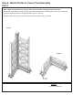
A: Attach one Beam End assembly from Step
8 to each Corner Post assembly with the cut-
out side facing out using one 1/4 x 4-1/4” Wafer
Bolt (with 5/16” at washer and 1/4” connector
nut)
Step 9: Attach Beams to Corner Post Assemblies
2 x (068) Beam 81-1/2” 38.1 x 139.7 x 2070.1 mm (2 x 6 x 81-1/2”)
HardwareWood Parts
Fig. 9.2
12 x #8 x 3” Wood Screw
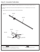
4 x 1/4 x 4-1/4” Wafer Bolt (5/16” at washer, 1/4” connector nut)
4 x 1/4 x 3-3/4” Wafer Bolt (5/16” at washer, 1/4” connector nut)
(068) Beam 81-1/2”
Beam End
Assembly
Fig. 9.1
#8 x 3”
Wood
Screw
Cut-out
Flat Washer
1/4 x 4-1/4”
Wafer Bolt
Flat Washer
Beam End
Assembly
Beam End
Assembly
(068) Beam
81-1/2”
Panel Post
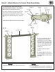
B: Fit one (068) Beam 81-1/2”
in between two Corner Post
Assemblies and attach to Beam
End assemblies and Panel Post
as shown in g. 9.1 and 9.2 with
one 1/4 x 3-3/4” Wafer Bolt (with
5/16” at washer and 1/4” con-
nector nut).
C: Attach six #8 x 3” Wood
Screws.
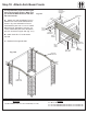
D: Repeat Steps A, B and C to
the opposite pair of Panel Corner
Post Assemblies to make a front
and back.
1/4 x 3-3/4”
Wafer Bolt
Note: Beams should be ush to top of posts.
Flush
Flush