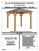
8’ x 8 MERIDIAN WOOD GAZEBO with ALUMINUM ROOF Installation and Operating Instructions — YM11827 IMPORTANT, RETAIN FOR FUTURE REFERENCE: READ CAREFULLY Revised 10-28-2021 ARTISTRY Artistry — North America Toll Free Customer Support: 1.888.509.4382 www.yardistrystructures.com HEIGHT: 2.
A\Important Safety Notice! Artistry components are intended for privacy, decorative and ornamental use only. Product is NOT INTENDED for the following: « A safety barrier to prevent unsupervised access to pools, hot tubs, spas or ponds. « As load bearing support for a building, structure, heavy objects or swings. « Used in structures that trap wind, rain or snow that would create extra load on the product. Accumulated snow must be removed from roof. DO NOT climb or walk on roof for any reason.
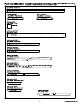
Limited Warren This Warranty gives you specific legal rights. You may have other rights as well which vary from state to state or province to province. This warranty excludes all consequential damages, however, some states/provinces do not allow the limitation or exclusion of consequential damages, and therefore this limitation may not apply to you.
Instructions for Proper Maintenance Your Artistry structure is designed and constructed of quality materials. As with all outdoor products it will weather and wear. To maximize the enjoyment, safety and life of your structure it is important that you, the owner, properly maintain it. HARDWARE: + Check metal parts for rust. If found, sand and repaint using a non-lead paint complying with 16 CFR 1303. + Inspect and tighten all hardware after completion of assembly; after first month of use; and then annually.
Assembly Tips Following are some helpful tips to make the assembly process smooth and efficient. PER-ASSEMBLIES: (i.e. Post and Beam Assemblies, Roof Rafter Assembly, etc) « Work on a raised, solid and flat surface such as, a table or saw horse. « Keep all connections flush where shown in the instructions. + When assembling the beams keep parts flat, straight and snug when connecting. METAL PARTS: + Roofing material may have sharp edges, wear safety gloves.
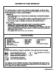
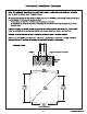
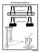
Permanent Installation Examples Note: It is critically important you start with square, solid and level footings, concrete pad or deck to attach your Pergola Room. We supply Post Mounts with this structure which gives you the flexibility to permanently install your structure to a per-existing or new wood or concrete surface. = The hardware to attach the Post Mount to the structure is included.
Permanent Installation Examples cont. Concrete Patio [min. 2.519 m x 2.519 m (8’ x 8’ with 15.24 cm (6”) clearance on all sides Anchoring Hardware not included \. A . Wood Deck [min. 2.519 m x 2.519 m (8’ x 8’ with 15.24 cm on all sides . . Anchoring Hardware not Included . . Post Mount Anchoring Hardware {not included) Post Mounts have a 1.27 cm diameter hole for anchoring hardware.
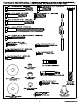
Part 1 identified cation Dimensions are approximate and are shown to assist in the identification of parts for ) assembly. Actual dimensions may be smaller or larger. 2159mm (857) 4pc. (1249) Block Post ° Y70131-1249 651mm 651mm 4pc. (1254) Right Gusset 4pc. (1255) Left Gusset & outdoors SN C7 vas Ny 165mm (61/27) 16pe. (802) Plinth Y50131-802 2213.9mm pc. (1240) Beam Y70131-1240 1230.7mm (48-7167) 4pc. (1242) Fascia Right [3 vsoratrzaz T. 1230.7mm (48-7167) 4pc.
Hardware Identification ( Dimensions are approximate and are shown to assist in the identification of parts for assembly. Actual dimensions may be smaller or larger. — 12pc. 1/4 x 2-3/4 Hex Bolt (YO7718-223) 4pe. Hex Bolt 5/16 x (Y07718-311) 7 12pe. 1/4 x 2" Hex Bolt (Y07718-220) (YO7718-310) 1 7] 16pe. Hex Bolt 5/16 x (Y07718-323) — spec. Lag Screw 5/16 x 4" (Y06218-340) 16pc. Lag Screw 1/4” x No.12 Shank | 82pc. Pan Screw #10 x HITTITE (Y08491-711) 120pe. Wood ! Screw #5 x D HAN 20pc.
Hardware Identity cation ( Dimensions are approximate and are shown to assist in the identification of parts for assembly. Actual dimensions may be smaller or larger. . Short Panel Left 4pe. Short Panel Right I (Y01033-498) (Y01033-495) 1pe. | Spring Clip | (Y09490-001) | 2pe. | Roof Peak Bracket | (Y00429-068) spec. | Peak Loop | (Y20018-003) 1pe. ! 1/4" Nut | (Y08490-200) | | 4po. Lo Prescript 4pe. Long Panel Left 15 Ripe.
Step 1: Inventory Parts Read This Before Starting Assembly A. This is the time for you to inventory all your hardware, wood and accessories, referencing the parts identification sheets. This will assist you with your assembly. + Each step indicates which bolts and/or screws you will need for assembly, as well as any flat washers, lock washers, t-nuts or lock nuts. B. If there are any missing or damaged pieces or you need assistance with assembly please contact the consumer relations department directly.
Step 2: Post Assemblies A: At the bottom of each (1249) Block Post insert two 5/16" T-Nuts as shown in F2.1 and F2.2. B: At the bottom of each (1249) Block Post place two Post Mounts tight to the bottom and inside faces as shown in F2.1 and F2.2. Loosely attach with one 5/16 x 1" Hex Bolt (with 5/16” lock washer and large washer) per mount so they connect fo the T-Nuts. C: On each side of the Posts, place one (802) Plinth flush to the bottom and attach with four #8 x Wood Screws per plinth.
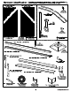
Step 3: Frame Assembly Part hard, flat surface place one (1240) Beam against the outside of two Post Assemblies, flush to the tops and outside comers. Bevels face away from the posts. Notice bolt holes are towards the bottom. Attach Beam to Post Assembly, through the bottom hole, with one 3/8 x Hex Bolt (with two 3/8" large washers and one 3/8” lock nut) per post. (F3.1 and F3.2) The distance from the outside of one Post Assembly to the outside of the second Post Assembly should be 7° (2.214m). See F3.
Step 3: Frame Assembly Da Part 2 % Note: The beveled ends on each gusset should always face away from the wood it Is F34 (1240) Beam attaching to. S C: Make sure each (1240) Beam is square with the Post Assemblies then facing one (1240) Beam from the outside place one (1254) Right Gusset on the right hand side so the top fits tight to the (1240) Beam and the bottom fits tight to the Post Assembly. Attach gusset to (1240) Beam with two 5/16 x Hex Bolts (with 5/16” lock washer, large washer and 5/16” t-nut).
Step 3: Frame Assembly Da Part 3 =% E: Make sure the assembly is still square then in the top holes of (1240) Beam per-drill with a 1/8” drill bit and attach to Post Assembly with two 5/16 x 4” Lag Screws (with large washer). (F3.6 and F3.7) F: Repeat Steps C E for second Side Assembly. (1240) Beam 516x4" Lag Screw Large Washer x = > Hardware 4 x 5116 x 4” Lag Craw large washer) 15 supportgRyardistrystiuciurss.
Step 3: Frame Assembly (A) ( Q Part 4 G: Move your Post Assemblies to the final location. Make sure the ground is flat and level before continuing assembly. H: Stand each Side Assembly then place one (1240) Beam against each post, flush to the tops and tight to the Side Assemblies. Notice bolt holes on (1240) Beam are towards the bottom. Attach beams to each post with one 3/8 x Hex Bolt (with two 3/8” large washers and one 3/8" lock nut) per post in the top holes.
Step 3: Frame Assembly Part 5 SEEN I: Make sure assembly is square then facing (1240) Beams from the outside place one (1254) Right Gusset on the right hand sides so the top fits tight to the (1240) Beams and the bottom fits tight to the Post Assemblies. Attach gussets to {1240) Beams with two 5/16 x 2-3/4 Hex Bolts {with 5/16" lock washer, large washer and 5/16” t-nut) per gusset. Pr-drill with a 1/8” drill bit then attach to Post Assemblies with two 1/4 x Lag Screws (with large washer) per gusset. (F3.
Step 3: Frame Assembly Part 6 K: Make sure the assembly is still square then in the bottom holes of each (1240) Beam per-drill with a 1/8” drill bit and attach to Post Assemblies with two 5/16 x 4” Lag Screw (with large washer) per beam. {F3.13 and F3.14) L: Depending on what you are placing the Gazebo on will determine how you anchor it fo that surface. Please refer to pages 6 and 7 for installation examples. F3.14 Any hardware or extra materials for mounting will have to be purchased in advance.
Step 4: Fascia Beam Assembly A: Tightly connect one (1241) Fascia Left and one (1242) Fascia Right using one 5/16 x Hex Bolt {with 5/16” lock washer, large washer and 5/16" t-nut) as shown in F4.1 and F4.2. B: Repeat Step A three more times to make four Fascia Beam Assemblies. F4.
Step 5: Roof Rafter Assembly Part 1 A: On each side of one (1248) Rafter place one (1244) Corner LT and one (1243) Comer RT so the tops and edges are flush then attach with two #8 x 2° Wood Screws per side. (F5.1 and F5.2) B: Place Fascia Beam Assembly from Step 4 on the bottom of (1244) Corner LT, (1243) Comer RT and (1248) Rafter so the sides are flush then attach with one #8 x 2" Wood Screw at each end, noticing which holes to be used.
Step 5: Roof Rafter Assembly Part 2 D: Place one (1245) Short Strap in the notches of (1244) Comer LT, (1243) Comer RT and (1248) Rafter so the ends do not overhang the outside edges of the outside boards then attach with six #8 x Wood Screws. Repeat for all four assemblies. (F5.5 and F5.6) (1245) Short Strap F5.5 Front View F5.6 #8 x 1-1/2 Wood Screws x6 per assembly (1243) Comer RT (1245) Short Strap (1248) Rafter Wood Parts Hardware 4 x (1245) Short Strap Wood Screw 21 supportgRyardistrystiuciurss.
Step 5: Roof Rafter Assembly Part 3 E: Place one (1246) Rafter Short Left and one (1247) Rafter Short Right flush to top of Fascia Beam Assembly and tight to (1244) Corner LT and (1243) Corner RT. Attach (1246) Rafter Short Left and (1247) Rafter Short Right to (1244) Corner LT and (1243) Comer RT with two #8 x Wood Screws per board and to Fascia Beam Assembly with one #8 x Wood Screw per board. Repeat for all four assemblies. (F5.7, F5.8 and F5.9) F5.8 F5.
Step 6: Attach Rafter Beam Brackets (with two large washers and one 1/4” lock nut). (F6.1 and F6.2) F6.1 al Rafter Beam Bracket A: On the back of three Roof Rafter Assemblies place one Rafter Beam Bracket on (1246) Rafter Short Left, (1247) Rafter Short Right and (1248) Rafter.
INSTALLING ROOFING MATERIAL CAUTION! Roofing material may have sharp edges! Wear gloves! HANDLE WITH CARE! Place roofing material on a non-abrasive surface before assembly as it can bend, dent and scratch easily. WARNING —DO NOT OVER TIGHTEN ROOFING SCREWS! Over tightening screws will cause roofing material to crush. Over lightened and Crushed Snug and Tight The roofing screws can easily crush the Roof Panels and Roof Edges when using a power drill.
INSTALLING ROOFING MATERIAL CAUTION! Roofing material may have sharp edges! Wear gloves! BE SURE TO REMOVE ALL PLASTIC COVERING, ON BOTH SIDES OF THE ALUMINUM PANELS AND TRIM, DIRECTLY BEFORE INSTALLING EACH PIECE. (One side is clear and the other is blue, both must be removed.
Step 7: Attach Roof Panels Part 1 A: Place one Long Panel Left on the front of one Roof Rafter Assembly so it is flush to the side of (1244) Comer LT and and a slight overhang at the bottom of the Fascia Beam Assembly. Holes should line up with (1248) Rafter. (F7.1 and F7.2) B: Place one Long Panel Right on Roof Rafter Assembly so it overlaps the Long Panel Left and it is flush to the side of (1243) Corner RT and a slight overhang at the bottom of the Fascia Beam Assembly. (F7.1 and F7.
Step 7: Attach Roof Panels Part 2 E: Place one Short Panel Left on Roof Rafter Assembly so it overlaps the Long Panel Left and it is flush to the sides of (1244) Comer LT and a slight overhang at the bottom of the Fascia Beam Assembly. There should be no overhanging at the comers. (F7.3 and F7.4) F: Place one Short Panel Right on Roof Rafter Assembly so it overlaps the Long Panel Right and it is flush to the side of (1243) Comer RT and a slight overhang at the bottom of the Fascia Beam Assembly.
Step 8: Attach Roof Edges A: Place ons Roof Edge Left and one Fascia Beam Roof Edge Left Roof Edge Right on the 7 7 are flush with the outside ends of the Fascia Beam Assembly an: Edges with Roofing Screws per Roof Rafter asses bottom of each Roof Rafter Assembly so the ends entree.
Step 9: Attach Ridge Clips n the inside of each Ridge Clip then Ridge Clip on each side of each ver the panels and ai with d Si Ridge Clip. The ge Clip to the m of ti 1,F9.2 and PAN Components: x Ridge Clip 85.
Step 10: Attach Roof Panels to Frame 1 Part 1 A: From inside the Post Assemblies measure 3' m) to mark the center of each (1240) Beam. (F10.1) B: With two assemblers place one Roof Panel Assembly with Rafter Beam Brackets just in front of the Posts then raise over (1240) Beam, taking care not to drag the panel on the beams. Make sure the middle Rafter Beam Bracket lines up to the center mark. (F10.1) Mark contra Roof Anal location Assembly F10.1 f n (1240) Beam * In front of (1240) Beam Q — Posts 32.
Step 10: Attach Roof Panels to Frame A 1 Part 2 C: Lift a second Roof Panel Assembly with Rafter Beam Brackets over (1240) Beam taking care not to drag the panel on the beams. Make sure the (1243) Comer RT and (1244) Comer LT are flush with each other. One person must remain on the center ladder to hold both panels In place until three panels are up and secure. (F10.2 and F10.
Step 10: Attach Roof Panels to Frame A 1 Part 3 E: Lift a third Roof Panel Assembly with Rafter Beam Brackets over (1240) Beam taking care not to drag the panel on the beams then set in place beside the second panel. (F10.5)} F: Starting at the bottom and working up connect Roof Panel Assemblies through (1243) Comer RT and (1244) Comer LT with three 1/4 x Hex Bolts (with two large washers and one 1/4” lock nut).
Step 11: Roof Peak Assembly A: Insert Carriage Bolt through the top of Peak Cap, into Peak Post then Spring Clip. The Spring Clip holds the assembly together. (F11.1) B: Insert 1/4” Nut into Peak Loop. Be careful nut is loose and will fall out until attached to Peak Cap Assembly. F11.2) F111 J er] F11.2 1" J Components; 1 x Roof Peak Set 1 x Peak Cap 1x Carriage Bolt 1 x Puck Post 1x Peak Loop 1 x Spring Clip 1x 33 supportgRyardistrystiuciurss.
Step 12: Attach Roof Peak to Roof Panels (A) 1] A: Insert Roof Peak Assembly in gap between Roof Panels. Peak Cap to be lined up with (1243) Comer RT and (1244) Corner LT. (F12.1 and F12.2) B: Insert both Roof Peak Brackets through Carriage Bolt and attach Peak Loop to Carriage Bolt and twist to tighten loosely. C: Loosely attach both Roof Peak Brackets to (1243) Comer RT and (1244) Comer LT in the slotted holes with two #10 x Pan Screws as shown in F12.3. F121 F12.2 Comer LT& F123 #10.
Step 13: Attach Final Roof Panel Part 1 A: Lift last Roof Panel Assembly (without Rafter Beam Brackets) over (1240) Beam taking care not to drag the panel on the beams. Panel fits under the Peak Cap, push up on Peak Loop to lift Peak Cap. The center of the other panels may have to be pushed up to fit fourth panel. (F13.1 and F13.2) B: Check again that Peak Cap is lined up with (1243) Corner RT and (1244) Comer LT. (F13.
Step 13: Attach Final Roof Panel (A) 1 Part 2 Remember to push up center to assist with alignment. C: Starting at the bottom and working up loosely connect Roof Panel Assemblies through (1243) Comer RT and (1244) Corner LT with three 1/4 x Hex Bolts (with two large washers and one 1/4” lock nut) per side. To align bolt holes helper on the center ladder may have to push up in the center of the panels and others make sure comers are aligned. Tighten bolts when all six have been installed. (F13.4 and F13.
Step 13: Attach Final Roof Panel " Part 3 D: On the fourth Roof Rafter Assembly, place one Rafter Beam Bracket on (1246) Rafter Short Left, (1247) Rafter Short Right and (1248) Rafter. Loosely attach each bracket to rafters with one 1/4 x 2° Hex Bolt (with two 1/45/16" large washers and one 1/4” lock nut). (F13.
Step 14: Secure Roof Corners 1 A: Make sure middle Rafter Beam Brackets are lined up over center mark and all are flush and tight to (1240) Beams. Lift in center if needed to adjust Roof Panel Assemblies. B: From outside the assembly attach Roof Panel Assemblies together at the Fascia Beam Assembly ends with two #8 x Wood Screws per comer. A helper may need to lift the center of the roof to bring the comers tight together. (F14.1 and F14.
Step 15: Attach Corner Caps each corner place one Comer Cap tight to Fascia Assemblies, push up so the bottom is tight to the bottom of the assemblies then attach with four #8 x 3/4" Sheet Metal Screws per Corner Cap. {F15.1 and F15.2) Sheet Metal rev #8 x 3/4” S Sheet Metal Screw Fascia Fascia Assembly Assembly Tight Components: Hardware 4 x Comer Cap 3/4” Sheet Metal Screw 39 supportgRyardistrystiuciurss.
Step 16: Secure Rafter Beam Brackets (A) 1 A: From inside the assembly attach Rafter Beam Brackets to beams and rafters with four #10 x Pan Screws per bracket. (F16.1 and F16.2) B: Tighten all bolts in Rafter Beam Brackets. (F16.1 and F16.2) F16.1 Inside View Beam F16.2 Rafter Tighten all Rafter Beam, Bracket bolts Rafter Beam #10 x Screw Beam Hardware Pan Screw 40 supportgRyardistrystiuciurss.
Step 17: Secure Roof Peak Brackets 1 A: Tighten the two screws in Roof Peak Brackets then attach to (1243) Comer RTs and (1244) Corner LTs in the remaining holes with fourteen #10 x Pan Screws. (F17.1) F171 Roof Peak Bracket Comer LT &RT #10x Pan Screw x 14 LT&RT Hardware Pan Screw 41 supportgRyardistrystiuciurss.
Step 18: Attach Ridge Caps to Roof Panels (A) Lu A: Slide one Ridge Cap over the Ridge Clips, with cut end leading, on each comer of the assembly from the bottom up, lifting Peak Cap by pushing up the Peak Loop so Ridge Caps fit under Peak Cap then attach with two #8 x 3/4" Sheet Metal Screws per Ridge Cap. (F18.1, F18.2 and F18.3) B: Tighten Loop to secure Roof Peak Set. Note: To help Ridge Caps slide on easier use a lubricant such as liquid soap. Ridge Clip F18.
Step 19: Attach Twist Brackets A: Attach 45° Twist Bracket LT or 45° Twist Bracket RT to posts and LT Comer Rafters and RT Corner Rafters with four #10 x Pan Screws per bracket, as shown in F19.1 and F19.2. F19.2 #10x Pan Screw Post Components: Hardware 2 x 45° Twist Bracket Pan Screw 2 x 45° Twist Bracket RT 43 supportgRyardistrystiuciurss.
Step 20: Metal Hooks and Plaque % J A: Two 50 mm Hooks are included with this unit for attaching wiring. They can be placed anywhere along the (1243) Comer RTs and (1244) Comer LTs as needed. Pr-drill with a 1/8” drill bit before installing. (F20.1 and F20.2) B: Attach Gazebo ID Plaque to a prominent location on your gazebo with two #10 x Pan Screws. This provides warnings concerning safety and important contact information.