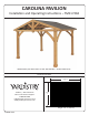
CAROLINA PAVILION Installation and Operating Instructions – YM11726X IMPORTANT, RETAIN FOR FUTURE REFERENCE: READ CAREFULLY Revised 03-10-2021 [39.624 m] 13’ Yardistry – North America Toll Free Customer Support: 1.888.509.4382 info@yardistrystructures.com www.yardistrystructures.com [3352.8] 11’ Height: 10’ 1” (3.
Important Safety Notice! Yardistry components are intended for privacy, decorative and ornamental use only. Product is NOT INTENDED for the following: •A safety barrier to prevent unsupervised access to pools, hot tubs, spas or ponds. • As load bearing support for a building, structure, heavy objects or swings. •U sed in structures that trap wind, rain or snow that would create extra load on the product. Accumulated snow must be removed from roof. DO NOT climb or walk on roof for any reason.
Limited Warranty Yardistry warrants that this product is free from defect in materials and workmanship for a period of one (1) year from the original date of purchase. In addition, for any product with lumber, all lumber is warranted for five (5) years against rot and decay. This warranty applies to the original owner and registrant and is non-transferable. Regular maintenance is required to assure the integrity of your product and is a requirement of the warranty.
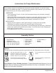
Instructions for Proper Maintenance Your Yardistry structure is designed and constructed of quality materials. As with all outdoor products it will weather and wear. To maximize the enjoyment, safety and life of your structure it is important that you, the owner, properly maintain it. HARDWARE: • • • Check metal parts for rust. If found, sand and repaint using a non-lead paint complying with 16 CFR 1303.
Assembly Tips Following are some helpful tips to make the assembly process smooth and efficient. PRE-ASSEMBLIES: (i.e. Post and Beam Assemblies, Roof Rafter Assembly, etc) • Work on a raised, solid and flat surface such as, a table or saw horse. • Keep all connections flush where shown in the instructions. • When assembling the beams keep parts flat, straight and snug when connecting. METAL PARTS: • Roofing material may have sharp edges, wear safety gloves.
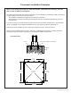
Permanent Installation Examples Note: It is critically important you start with square, solid and level footings, concrete pad or deck to attach your Pavilion. We supply Post Mounts with this structure which gives you the flexibility to permanently install your structure to a pre-existing or new wood or concrete surface. • The hardware to attach the Post Mount to the structure is included. • The hardware to mount the structure permanently will need to be purchased separately at your local hardware store.
Permanent Installation Examples cont. Concrete Patio (min. 11’7” x 12’) with 6” clearance on all sides Anchoring Hardware not included Wood Deck (min. 11’ 7” x 12’) with 6” clearance on all sides Anchoring Hardware not included Post Mount Anchoring Hardware (not included) Post Mounts have a 1/2” diameter hole for anchoring hardware. 7 support@yardistrystructures.
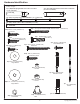
are approximate and are shown to assist in the identification of parts for Part Identification ( Dimensions ) assembly. Actual dimensions may be smaller or larger. 16pc. (422) Plinth 19.1 x 133.4 x 190.5mm (3/4 x 5-1/4 x 7-1/2") Y50131-422 2pc. (476) Gusset Support 25.4 x 139.7 x 1724mm (1 x 5½ x 67-7/8") Y50131-476 4pc. (470) Rafter Brace 25.4 x 97.6 x 513.2mm (1 x 3-27/32 x 20-13/64) Y50131-470 2pc. (469) Rafter Top Short 25.4 x 88.9 x 1378.3mm (1 x 3½ x 54-17/64mm) Y50131-469 4pc. (471) Gable End 25.
Hardware Identification Dimensions are approximate and are shown to assist in the identification of parts for assembly. Actual dimensions may be smaller or larger. 2pc. (477) Gable Upright Front 88.9 x 139.7 x 796.5mm (3½ x 5½ x 31-23/64") 2pc. (480) Gable Upright Back 76.2 x 139.7 x 813.3mm (3 x 5½ x 32-1/64") Y70131-477 Y70131-480 6pc. (465) Long Strap 31.8 x 76.2 x 2195.5mm (1¼ x 3 x 86-7/16") Y50131-465 4pc. (696) - M Post 152.4 x 152.4 x 2336.8mm (6 x 6 x 92") Y70131-696 24pc.
Hardware Identification Dimensions are approximate and are shown to assist in the identification of parts for assembly. Actual dimensions may be smaller or larger. 10pc. Hex Bolt 1/4 x 2" - (Y07718-220) 4pc. Hex Bolt 1/4 x 2-3/4" - (Y07718-223) 4pc. Hex Bolt 1/4 x 4-3/4" - (Y07718-243) 12pc. Hex Bolt 5/16 x 1-1/2" - (Y07718-312) 8pc. Hex Bolt 5/16 x 2-1/4" - (Y07718-321) 12pc. Hex Bolt 5/16 x 4" - (Y07718-340) 4pc. Lag Screw 5/16 x 4-3/4" - (Y06218-343) 4pc.
Hardware Identification ( Dimensions are approximate and are shown to assist in the identification of parts for assembly. Actual dimensions may be smaller or larger. ) 2pc. Ridge Cap Short 21.7 (Y01033-155) 4pc. Ridge Clip Short (Y01033-154) 2pc. Roof Edge Left (Y01033-152) 1pc. Roof Panel Set Y70833-164 6pc. Main Panel - Y01033-164 2pc. Right Side Panel - Y01033-165 2pc. Roof Edge Right (Y01033-153) 1pc.Ridge Cap 91 (Y01033-117) 1pc. Yardistry Plaque (Y70800-104) 1pc.
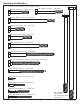
Step 1: Inventory Parts - Read This Before Starting Assembly STOP A. STOP STOP STOP his is the time for you to inventory all your hardware, wood and accessories, T referencing the parts identification sheets. This will assist you with your assembly. • Each step indicates which bolts and/or screws you will need for assembly, as well as any flat washers, lock washers, t-nuts or lock nuts. B.
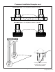
Step 2: Post Assemblies Avery Inst 1 - Post Assembly A: At the bottom of one (696) 6 x 6 Post insert two 5/16” T-Nuts as shown in fig. 2.1. B: At the bottom of the same (696) 6 x 6 Post place two Post Mounts tight to the bottom and inside faces as shown in fig. 2.1 and 2.2. Loosely attach with one 5/16 x 1-1/4” Hex Bolt (with 5/16” lock washer and 1/4-5/16” large washer) per mount so they connect to the T-Nuts.
Step 3: Beam Assembly - Front/Back Savannah Inst 2 - Beam Assembly - Front/Back A: Fit together two (474) Gable Beams so the notched out ends are tight together then place one (477) Gable Upright Front on one side and one (480) Gable Upright Back and one (476) Gusset Support on the other side. Loosely attach with two 5/16 x 4” Hex Bolts (with 5/16” lock washer, 1/4-5/16” large washer and 5/16” t-nut) from the front of the assembly. Note: Bolt holes to the bottom of each (474) Gable Beam (fig. 3.1 and 3.
Step 4: Beam Assembly - Side Part 1 A: Fit two (475) Outside Beams together so the middle pilot holes are at the bottom for both. Connect using two 5/16 x 1-1/2” Hex Bolts (with 5/16” lock washer, 1/4-5/16” large washer and 5/16” t-nut) as shown in fig. 4.1. B: Connect one (473) Inside End Beam to each end of one (472) Inside Centre Beam 92 using two 5/16 x 1-1/2” Hex Bolts (with 5/16” lock washer, 1/4-5/16” large washer and 5/16” t-nut) per end as shown in fig. 4.2.
Step 4: Beam Assembly - Side Part 2 D: Place one Beam Outside Assembly and one Beam Inside Assembly so the ends are flush. Match the bolt holes in each (473) Inside End Beam with the bolt holes in each (475) Outside Beam. Attach assemblies with 12 #8 x 2-1/2” Wood Screws. (fig. 4.3) Avery Inst 3 - Beam Assembly - Side E: Repeat Step D one more time to make a second Beam Assembly - Side. (473) Inside Beam End Flush Fig. 4.3 Match bolt holes Hint: Use bolts at both ends to line up bolt holes.
x3 Step 5: Frame Assembly and Anchoring Part 1 A: Move your Post Assemblies to the final location. Make sure the ground is flat and level before continuing assembly. B: With one person at each Post stand two complete Post Assemblies. A third person places one Beam Assembly - Side against the outside of each Post, flush to the tops and outside corners. Notice bolt hole orientation on the assemblies.
Step 5: Frame Assembly and Anchoring Part 2 E: Make sure each corner is square and level then attach Beam Assembly - Side to Post Assemblies with one 5/16 x 4-3/4” Lag Screw (with 1/4-5/16” large washer) per corner and Beam Assembly - Front/Back to Post Assemblies with one 5/16 x 3” Lag Screw (with 1/4-5/16” large washer) per corner as shown below. (fig. 5.4) F: Depending on what you are placing the Pavilion on will determine how you anchor it to that surface.
Step 6: Attach Gussets Note: The bevelled ends on each gusset should always face away from the wood it is attaching to. A: Make sure the assembly is still square and level then facing one Beam Assembly - Side place one (706) Gusset Left on the right hand side so the top fits tight to the Beam Assembly - Side and the bottom fits tight to the Post Assembly. Attach gusset to Beam Assembly - Side with two 5/16 x 4” Hex Bolts (with 5/16” lock washer, 1/4-5/16” large washer and 5/16” t-nut).
Step 7: Frame Roof Panel Part 1 Avery Inst 6A - Frame Roof Panel A: Lay out 7 (468) Rafters on a hard flat surface as shown in fig. 7.1. You will need lots of room for this step. -Long Frame Panel on the last. Be Avery sure wider gap on6A (465) Strap is on Roof the first (468) Rafter.
Step 7: Frame Roof Panel Part 2 Avery Inst 6A - Frame Roof Panel D: Tight to each (465) Long Strap place one (466) Short Strap and tight to the first (466) Short Strap place one (465) Long Strap. Make sure the wider gap on each strap is on the outside. Make sure the assembly is square, pre-drill the first (466) Short Strap with a 1/8” drill bit, as shown below, then attach both (466) Short Straps with six #8 x 1-3/4” Wood Screws per board and (465) Long Strap with ten #8 x 1-3/4” Wood Screws.
Step 7: Frame Roof Panel Part 3 F: Make sure frame is square. Measurements to be as shown in fig. 7.6. G: In the two middle gaps between (468) Rafters place one (470) Rafter Brace flush to the top of (469) Rafter Top Short and (467) Rafter Top. Use two 1/4 x 4-3/4” Hex Bolts per brace as a guide to line up the bolt holes. Attach (470) Rafter Braces to (469) Rafter Top Short and (467) Rafter Top with eight #8 x 1-3/4” Wood Screws per brace.
STOP STOP STOP STOP INSTALLING ROOFING MATERIAL CAUTION! Roofing material may have sharp edges! Wear gloves! HANDLE WITH CARE! Place roofing material on a non-abrasive surface before assembly as it can bend, dent and scratch easily. WARNING – DO NOT OVER TIGHTEN ROOFING SCREWS! Over tightening screws will cause roofing material to crush. Overtightened and Crushed Snug and Tight X The roofing screws can easily crush the Roof Panels and Roof Edges when using a power drill.
STOP STOP STOP STOP INSTALLING ROOFING MATERIAL CAUTION! Roofing material may have sharp edges! Wear gloves! BE SURE TO REMOVE ALL PLASTIC COVERING, ON BOTH SIDES OF THE ALUMINUM PANELS AND TRIM, DIRECTLY BEFORE INSTALLING EACH PIECE. (One side is clear and the other is blue, both must be removed.) Example #1 Example #2 Overtightened and Crushed Snug and Tight Example #3 24 support@yardistrystructures.
Step 8: Attach Roof Panels Part 1 Note: Be sure to remove all plastic covering on both sides of the metal panels directly before installing each piece. A: Make sure panel is still square then on one Roof Panel Frame place one Main Panel flush to the top and sides of the outside (468) Rafter on the side shown below. Panels should be flush to the top of the (467) Rafter Top and (469) Rafter Top Short. There will be approximately a 5/16” overhang at the bottom.
Step 8: Attach Roof Panels Part 2 E: Place one Roof Edge Left and one Roof Edge Right on the bottom of one Roof Panel Frame so they meet tight and the ends are flush with the outside ends of (466) Short Strap and (465) Long Strap. Predrill the end hole on Roof Edge Left with a 1/8” drill bit then attach both Roof Edges with 16 #8 x 1” Hex Roofing Screws. (fig. 8.4 and 8.5) Savannah Inst 6C - Attach Roofing Trim Savannah Inst 6C - Attach Roofing Trim Fig. 8.
Step 8: Attach Roof Panels Part 3 F: Attach the three Main Panels and one Right Side Panel to Roof Panel Frame using 48 #8 x 1” Hex Roofing Screws as shown in fig. 8.6. On the left outside (468) Rafter, in between the screw holes, three additonal screws are to be inserted through the panels in the spaces indicated below (see A). Be sure not to overtighten screws. #8 x 1” Hex Roofing Screws (51 per Panel Frame) Fig. 8.
Step 8: Attach Roof Panels Part 4 G: Place Weather Seal on the inside of two Ridge Clip Short then place one Ridge Clip Short flush to each side of Roof Panel Frame and 2-3/4” up from the bottom of (467) Rafter Top and (469) Rafter Top Short, make sure not to compress Weather Seal. Attach with three #7 x 3/4” Wood Screws per Ridge Clip Short. Ridge Clip Shorts must cover the Roof Panels. (fig. 8.7, 8.8, 8.9 and 8.
x3 Step 9: Attach Roof Panels to Frame Part 1 A: With four assemblers lift one Roof Panel Frame up and over Post and Beam Frame Assembly so the notches in (468) Rafters rest on Beam Assembly - Side and (467) Rafter Top and (469) Rafter Top Short are flush to the outside of each (480) Gable Upright Back. One assembler must remain on a ladder to hold Roof Panel Frame in place until secured. (fig. 9.1, 9.2 and 9.
X X x3 Step 9: Attach Roof Panels to Frame Part 2 C: From inside the assembly attach the two Roof Panel Frames together through each (470) Rafter Braces with four 1/4 x 4-3/4” Hex Bolts (with two 1/4-5/16” large washer and one 1/4” lock nut) and through (467) Rafter Tops and (469) Rafter Top Shorts with four 1/4 x 2-3/4” Hex Bolt (with two 1/4-5/16” large washer and one 1/4” lock nut). (fig. 9.4, 9.5, 9.6 and 9.7) Fig. 9.4 X X 1/4 x 2-3/4” Hex Bolt Fig. 9.
x3 Step 9: Attach Roof Panels to Frame Part 3 D: Loosely attach each of the centre (468) Rafters to the inside of each Beam Assembly - Side with one Rafter Beam Bracket per (468) Rafter using one 1/4 x 2” Hex Bolt (with two 1/4-5/16” large washer and one 1/4” lock nut) per bracket. Push up on the centre of the Roof Panels so the notches in (468) Rafters are tight to the Beam Assembly - Side then attach four #10 x 1-1/4” Pan Screws per bracket. Once screws are installed tighten bolts. (fig. 9.8, 9.9 and 9.
Step 10: Attach Ridge Caps Part 1 x2 A: Slide Ridge Cap over the Ridge Clips towards the centre of the roof. (fig. 10.1 and 10.2) B: With the swaged end facing in slide one Ridge Cap Short at each end of the roof over the Ridge Clips. Use the swaged end to help push the Ridge Cap to the centre of the roof. Each Ridge Cap Short should be flush to the outside edge of the roof. (fig. 10.1, 10.3 and 10.4) Ridge Ridge Clip Clip Short Fig. 10.
Step 10: Attach Ridge Caps Part 2 x2 C: Make sure the Ridge Cap Shorts are flush to the outside edge of the roof then attach each end of the Ridge Cap to each Ridge Cap Short with two #8 x 3/4” Metal Screws per side. (fig. 10.5, 10.6 and 10.7) Fig. 10.5 Ridge Cap Short Fig. 10.6 Fig. 10.7 #8 x 3/4” Sheet Metal Screw Ridge Cap Ridge Cap Short Flush Ridge Cap Hardware 4 x #8 x 3/4” Sheet Metal Screw 33 support@yardistrystructures.
x2 Step 11: Attach Gable Ends A: On one side of the assembly place two (471) Gable Ends against the outside (468) Rafters so the peaks meet in the centre and they are tight and flush to the top and edge of (477) Gable Upright Front. Bottom of (471) Gable End to bottom of (468) Rafter should measure 1” all along each (471) Gable End. Attach with ten #8 x 1-3/4” Wood Screws per (471) Gable End. (fig. 11.1, 11.2 and 11.
Step 12: Attach Gable Gussets A: From inside the assembly place one (414) Gable Gusset on each side of (480) Gable Upright Back so it is resting on (471) Gable End, tight to (480) Gable Upright Back and tight and flush to (468) Rafter. (fig. 12.1 and 12.2) B: Attach each (414) Gable Gusset to (471) Gable End with two #8 x 1-3/4” Wood Screws per gusset and to (480) Gable Upright Back with one #10 x 4” Wood Screw per gusset. (fig. 12.1 and 12.
Step 13: Truss Assemblies Part 1 A: Place one (417) Tie Brace centred, tight and square to the top of (416) Tie. Attach (416) Tie to (417) Tie Brace using two Jamb Mounts (one per side) with four #8 x 1” Pan Screws per mount. Repeat to complete five Tie Brace Assemblies. (fig. 13.1 and 13.2) B: Attach one Tie Wrap Bracket to each end of each (416) Tie with one #10 x 1-1/4” Pan Screw per bracket using the inside holes. (416) Tie is tight to end of bracket. (fig. 13.
Step 13: Truss Assemblies Part 2 C: Attach one Tie Centre Bracket to the peak of four (468) Rafter, (467) Rafter Top, (469) Rafter Top Short with four #8 x 1” Pan Screws per bracket. Notice that three Tie Centre Brackets face one way and one faces the opposite side. It will only fit on this side. (fig. 13.3 and 13.4) Notice Tie Centre Bracket on opposite side for this location Fig. 13.3 This bracket does not get installed until Step 13, Part 4 Roof Panel removed for clarity Tight (467) Rafter Top Fig.
Step 13: Truss Assemblies Part 3 x2 D: With a helper place five (416) Tie with brackets tight against (468) Rafters so (417) Tie Braces fit into Tie Centre Brackets. Make sure (416) Ties are level then attach Tie Wrap Brackets to (468) Rafters with two #10 x 1-1/4” Pan Screws on both sides of each bracket and one #12 x 1-1/4” Pan Screw on one side of each bracket. (fig. 13.5, 13.6, 13.7 and 13.
Step 13: Truss Assemblies Part 4 F: Secure four (417) Tie Braces to each Tie Centre Bracket with two #8 x 1” Pan Screws per bracket. (fig. 13.9 and 13.10) G: Secure remaining (417) Tie Brace to (467) Rafter Top and (469) Rafter Top Short with one Corner Bracket using four #8 x 1” Pan Screws. (fig. 13.9 and 13.11) #8 x 1” Pan Screw Fig. 13.10 Tie Centre Bracket Fig. 13.9 (417) Tie Brace Roof Panel removed for clarity Tight Fig. 13.
Step 14: Attach Plaque A: Attach Yardistry Plaque to a prominent location on your Pavilion with two #8 x 1” Pan Screws. This provides warnings concerning safety and important contact information. A tracking number is provided to allow you to get critical information or order replacement parts for this specific model. (fig. 14.1 and 14.2) Fig. 14.1 #8 x 1” Pan Screw Fig.14.2 Yardistry Plaque Componets: 1 x Yardistry Plaque 40 Hardware 2 x #8 x 1” Pan Screw support@yardistrystructures.
NOTES 41 support@yardistrystructures.
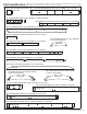
Customer Registration Card - Tarjeta de Registro del Cliente - Carte d’inscription du client First Name - Primer Nombre - Prénom Initial - Incial - Initiale Street - Calle - Rue Last Name - Apellido - Nom de famille PO Box - Casilla postal Boîte postale City - Ciudad - Ville Apt. No. - App.