Save This Manual for Future Reference Single-Stage Snow thrower Operator’s Manual MODEL NUMBER YB4628 SERIAL NUMBER PURCHASE DATE Both model number and serial number may be found on the main label. You should record both of them in a safe place for future use.
Your new YARDMAX™ snow thrower offers quality construction, and is easy and safe to operate. With proper use and care, it is designed to give you many years of dependable service.
Single-Stage Snow Blower Carefully read through this entire operator's manual before using your new unit. Pay attention to all cautions and warnings. This unit is a gasoline engine driven snow thrower. It is perfect for tackling light to medium snow fall - easily able to remove snow up to 11" deep. It is easy and safe to operate. With proper use and care, it should give you many years of dependable service.
SUPPORT Have questions about your YARDMAX equipment? Call us at 844-YARDMAX, email us at support@yardmax.com, or contact us via your favorite social media site.
Single-Stage Snow Blower » Operator’s Manual SYMBOLS The rating plate on your machine may show symbols. These represent important information about the product or instructions on its use. Read these instructions carefully. Wear eye protection. Wear hearing protection. Do not remove or tamper with the protection and safety devices. No smoking, sparks, or ćames. Wear safety footwear. Do not touch parts which are hot from operation. Serious burns may result. Keep children and bystanders off and away.
SAFETY GENERAL SAFETY RULES UNDERSTAND YOUR MACHINE 5HDG WKLV PDQXDO DQG ODEHOV DIĆ[HG WR WKH PDFKLQH WR XQGHUVWDQG its limitations and potential hazards. Be thoroughly familiar with the controls and their proper operation. Know how to stop the machine and disengage the controls quickly. Make sure to read and understand all the instructions and safety precautions as outlined in the Engine Manufacturer’s manual packed separately with your unit.
Single-Stage Snow Blower ENGINE SAFETY This machine is equipped with an internal combustion engine. Do not use on or near any unimproved, forest covered, or brush FRYHUHG ODQG XQOHVV WKH H[KDXVW V\VWHP LV HTXLSSHG ZLWK D VSDUN arrester meeting applicable local, state, or federal laws. In the state of California, a spark arrester is required by law. Other states have similar laws. A spark arrester, if used, must be maintained in effective working order by the operator.
SPECIFIC SAFETY RULES Do not operate without wearing adequate winter outer garments. 6WD\ DOHUW IRU KLGGHQ KD]DUGV RU WUDIĆF Do not use the machine on a roof. Do not overload machine capacity by attempting to clear snow at too fast of a rate. 'R QRW UXQ WKH HQJLQH LQGRRUV H[FHSW ZKHQ VWDUWLQJ WKH HQJLQH and for transporting the snow thrower in or out of the building. 2SHQ WKH RXWVLGH GRRUV H[KDXVW IXPHV DUH GDQJHURXV Always check overhead and side clearances carefully before operation.
Single-Stage Snow Blower » Operator’s Manual CONTENTS SUPPLIED Your YARDMAX snow thrower comes partially assembled and contains the following: 1 6 2 7 HARDWARE KIT 3 1. Main Machine 2. Handlebars 4 5 8 8. Hardware Kit, Including ST6.3 X 25 3. Discharge Chute 4. Directional Chute Control Handle 5. Wheels M8 X 45 X4 1 X2 2 X4 3 6. Operator’s Manual & Engine Manual TOUCH-UP PAINT 7.
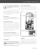
ASSEMBLY This snow thrower was partially assembled at the factory. To assemble your machine follow the below instructions. DISCHARGE CHUTE Do not overtighten the screws; otherwise you may damage the discharge chute and prevent it from turning freely. 1. Align the screw holes and the pin holes with the plastic studs in the chute base with the holes in the lower chute. 2. Secure with the self-tapping screws on the front, or open side, RI WKH FKXWH DQG WKH EDFNVLGH ĆUVW 3.
Single-Stage Snow Blower » Operator’s Manual HANDLEBAR RECOIL STARTER 1. Align the holes in the handlebars and the holes in the lower handle. Note Figure 3a below that the handle must face upward to work properly. 1. Slowly pull the recoil starter handle up towards the eye bolt. 2. Slip the recoil starter rope into the eye bolt from the back of the snow thrower. Figure 4 AUGER CLUTCH 1. Remove the cable adjuster link from the hole in the auger clutch handle. Figure 3a 2.
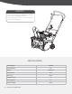
KNOW YOUR MACHINE FEATURES AND CONTROLS Auger Clutch Cable Adjuster Link Recoil Start Handle Fuel Filler Cap Chute Handle &KXWH 'HćHFWRU Discharge Chute Auger Scraper Blade Belt Cover Throttle Control Lever Primer Safety Ignition Switch Oil Drain Plug Engine Oil Fill Cap w/Dipstick 11 | Know Your Machine
Single-Stage Snow Blower DISCHARGE CHUTE » Operator’s Manual To disengage the auger, release the auger clutch. Grasp the chute handle and rotate the discharge chute to the left or right. A tension plate holds the chute in the desired position. Figure 7b Figure 6 Figure 7c AUGER & SCRAPER BLADE Do not use the chute handle to lift the unit. CHUTE DEFLECTOR /RRVHQ WKH GHćHFWRU ZLQJ NQRE DQG DGMXVW WKH FKXWH deflector up or down to control the snow discharge height and distance.
CHOKE SCRAPER BLADE Engage choke by rotating lever to CLOSED position whenever you are starting a cold engine. As engine warms up, gradually rotate the choke to the OPEN position. When the snow thrower is on a level surface the wheels, scraper blade, and auger should all contact the surface. If the scraper blade is adjusted too high, snow may blow under the housing.
Single-Stage Snow Blower » Operator’s Manual AUGER CLUTCH The auger will not turn unless the auger clutch is engaged. The auger must stop within 5 seconds after the auger clutch is released. The clutch cable must contain some slack when you disengage the clutch lever for the auger to stop properly. Spring Cover Spring Hook If the auger no longer turns when the auger clutch is engaged or if the belt slips under load, the auger cable or belt may have stretched.
OPERATION STARTING AND STOPPING THE ENGINE Before starting the engine, check engine oil level and ensure the engine is maintained as described in the Engine Manual with the snow thrower. COLD START – RECOIL STARTER 1. Be sure fuel shutoff valve is in the OPEN position. 2. Place ON / OFF switch in ON position. 3. Rotate choke control to CLOSED position. 4. Push the primer 2 or 3 times. When temperature is below 15°F (-25°C), additional priming may be needed.
Single-Stage Snow Blower » Operator’s Manual MAINTENANCE At the end of the season or if the Snow thrower will not be used for 30 days longer, follow the storage instructions below. ENGINE Refer to the Engine Operator’s Manual. 1. Run the engine until the fuel lines and carburetor are empty and it stops due to lack of fuel. LUBRICATION Lubricate the pivot points on the auger clutch lever and the spring at the end of the clutch cable with a light oil once every season before off-season storage. 2.
4. With the help of another pushing down the belt tension idler to keep the idler bracket away from the auger pulley, use two screwdrivers to pry the auger pulley as shown, so that auger SXOOH\ EHFRPHV ORRVH DQG DZD\ IURP WKH D[OH 6HH Figure 10c) Belt Keeper X2 Figure 10e 8. Replace the screws and washers and tighten securely. Turn the auger to ensure no interference. 9. Reinstall the belt cover removed earlier.
Single-Stage Snow Blower » Operator’s Manual TROUBLESHOOTING Problem Engine fails to start Cause Remedy 1. Choke not in CHOKE position 1. Move choke to CHOKE position 2. Engine not primed 2. Prime engine as instructed in this manual (QJLQH LV ćRRGHG 3. Wait a few minutes before restarting, do not prime 4. Spark plug wire loose or disconnected 4. Connect or tighten spark plug wire 5. Fuel tank empty or stale fuel. 5. Fill tank with clean, fresh gasoline 6. Faulty spark plug 6.
Problem Auger fails to stop within 5 seconds after auger clutch is released Cause Auger clutch cable out of adjustment Adjust auger clutch cable. 1. Discharge chute clogged. 1. Unclog discharge chute 2. Auger jammed 2. Remove debris or foreign object from auger 3. Auger clutch cable not adjusted properly Snow thrower fails to discharge snow 19 | Troubleshooting Remedy 3. Adjust auger clutch cable 4. Auger belt loose or damaged 4. Replace auger belt 5. Auger rubber paddles worn or damaged 5.
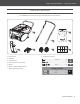
Single-Stage Snow Blower » Operator’s Manual PARTS DIAGRAM Parts Diagram | 20
PARTS LIST No. 21 | Description QTY. No. Description QTY. 1 Bearing Cup 2 39 Roller Bushing 1 2 %ROW 0 [ 10 40 .
Single-Stage Snow Blower No. Description QTY. No. » Description Operator’s Manual QTY.
yardmax.com Tame the Great Outdoors TM 1850 W Winchester Rd, Suite 106 | Libertyville, IL 60048 | 844-YARDMAX (844-927-3629) | info@yardmax.