
Instructions / Assembly

ASSEMBLY
This trackbarrow was partially assembled at the factory. To assemble your machine and the optional plow blade follow the below instructions.
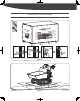
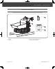
PLOW BLADE (OPTIONAL)
Figure 3a
Figure 3b
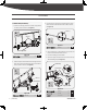
Figure 3c
Figure 3d
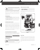
1. Mount the mounting bracket to the blade using M8×30
hex bolts, washers and nuts. (See Figure 3a)
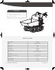
3. Insert the shorter control lever into the longer lever. Align
holes and fasten with M8×40 hex bolt, washers and nut.
(See Figure 3c)
4. Attach control lever to the guide tube. Line up holes and
fasten with M8×35 bolt, washers and nut.
5. Insert the handle grip into the holder.
6. Secure the support bracket into the control lever with pin
10×60 and bridge clip. (See Figure 3d)
2. Position the pivot bracket inside the mounting bracket and
align with mounting bracket holes. Secure with M20×95
hex bolt, washers and nut. (See Figure 3b)
M8 × 30 × 4
1
M8 × 40 × 1
3
M20 × 95 × 1
2
M8×30 (×4)
Mounting Bracket
M8 × 35 × 1
4
10 × 60 × 1
2 × 11 × 35 × 1
17
mm
18
mm
30
mm
13
mm
11
mm
× 2
M20×95 (×1)
Pivot Bracket
17
mm
18
mm
30
mm
13
mm
11
mm
× 2
YDB803PM02 - 1712
M8×40 (×1)
17
mm
18
mm
30
mm
13
mm
11
mm
× 2
Support Bracket
Control Lever
Handle Grip
10×60 (×1)
M8×35 (×1)
17
mm
18
mm
30
mm
13
mm
11
mm
× 2
9
YD8103PM03 - 1802
|
Assembly