Save This Manual for Future Reference Dual Rotating Rear Tine Tiller Operator’s Manual MODEL NUMBER YT4565 SERIAL NUMBER PURCHASE DATE Both model number and serial number may be found on the main label (see Page 2, Figure 1). You should record both of them in a safe place for future use. FOR YOUR SAFETY READ AND UNDERSTAND THE ENTIRE MANUAL BEFORE OPERATING MACHINE Tame the Great Outdoors TM 32850US25M102.
Your new YARDMAX™ dual rotating rear tine tiller offers quality construction, and is easy and safe to operate. With proper use and care, it is designed to give you many years of dependable service.
Dual Rotating Rear Tine Tiller » Operator’s Manual MODEL AND SERIAL NUMBERS Carefully read through this entire operator's manual before using your new unit. Pay attention to all cautions and warnings. This machine is a gasoline engine driven rear tine tiller. It is a durable, versatile and efficient machine, and it is both easy and safe to operate. With proper use and care, it should give you many years of dependable service.
support Have questions about your YARDMAX equipment? Call us at 844-YARDMAX, email us at support@yardmax.com, or contact us via your favorite social media site. Specifications Model Number Engine 208 cc Start Type Recoil Fuel Tank Size .75 gal Transmission Chain Gear Tire Size Tines 1 Forward / 1 Reverse 13" × 5" 10 Tiller, 2 Hammer Tine Direction Dual Rotation Tine Diameter 13" Depth Adjustments Tine RPM 7 Positions 190 RPM Tilling Width 18" Tilling Depth 6.
Dual Rotating Rear Tine Tiller » Operator’s Manual Symbols The rating plate on your machine may show symbols. These represent important information about the product or instructions on its use. Read these instructions carefully. No smoking, sparks, or flames. Wear eye protection. Do not touch parts that are hot from operation. Serious burns may result. Wear hearing protection. Wear protective gloves. Keep your feets clear from all rotating parts. Wear safety footwear.
Always keep hands and feet away from all moving parts during operation. Moving parts can cut or crush body parts. Always keep hands and feet away from all pinch points. Do not touch parts that might be hot from operation. Allow parts to cool before attempting to maintain, adjust, or service. Stay alert, watch what you are doing, and use common sense when operating the machine. Do not overreach. Do not operate the machine while barefoot or when wearing sandals or similar lightweight footwear.
Dual Rotating Rear Tine Tiller » Operator’s Manual SPECIFIC SAFETY RULES Thoroughly inspect the area to be tilled, and remove all debris and hard or sharp objects such as stones, sticks, glass, wire, bones, etc. Do not operate tiller in soil with large rocks and foreign objects which can damage the machine. Do not till above underground electric cables, telephone lines, water lines, gas lines, pipes, or hoses. If in doubt, contact your utility or telephone company to locate underground services.
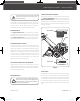
CONTENTS SUPPLIED Your YARDMAX rear tine tiller comes partially assembled and contains the following: 2 5 3 1 6 HARDWARE KIT 4 1. Main Machine 7 7. Hardware Kit, Including: 2. Operation Handle ×2 1 ×1 2 ×1 3 3. Shift Rod 4. Depth Stake M8 × 25 5. Operator's Manual & Engine Manual 6. Tools for Spark Plug Assembly TOUCH-UP PAINT 7 | Contents Supplied 32850US25M102.
Dual Rotating Rear Tine Tiller » Operator’s Manual ASSEMBLY This rear tine tiller was partially assembled at the factory. To assemble your machine follow the below instructions. OPERATION HANDLE The M8×75 bolts and nuts have been fixed in the guide bracket for shipping. First, remove the M8x75 bolts and nuts from the guide bracket. Then, align the holes in the operation handle shaft with the holes in the guide bracket and re-insert the M8x75 bolts and screw nuts to tighten.
DEPTH STAKE 1. Hold the machine leaning forward. (see Figure 5a, Illustration 1) 6. Adjust the depth stake to the desired depth of tilling. (See Figure 5b) 2. Pull the pin lever to unlock position. (see Figure 5a, Illustration 2) Limiter 3. Insert the depth stake into the slot in the blade cover. (see Figure 5a, Illustration 3) Transport Position 4. R elease the pin into the fourth hole of depth stake. At the same time, switch the pin lever to the lock position.
Dual Rotating Rear Tine Tiller » Operator’s Manual KNOW YOUR MACHINE FEATURES AND CONTROLS Throttle Control Shift Lever Drive Control Bar Operation Handle Handle Height Adjustment Drag Bar Depth Stake Outer Side Shield Tines Leveling Shield Recoil Starter Handle Throttle Control Choke Control Fuel Shut-Off Valve YT4565PM02 - 1704 32850US25M102.
DRIVE CONTROL BAR SHIFT LEVER The shift lever has 5 positions: 3 for transport only (no tine rotation) and 2 for operating the tines in forward (F) or reverse (R): . Moving the shift lever to the far left "F" position will ) when cause the tines to rotate clockwise ( you engage the drive control bar. This position is for tilling soft ground or pre-tilled soil. Moving the shift lever to the far left "R" position will cause the tines to rotate counter-clockwise ( ) when you engage the drive control bar.
Dual Rotating Rear Tine Tiller » Operator’s Manual OPERATION ADD OIL TO ENGINE IMPORTANT: DO NOT OVERFILL! The engine is shipped without oil. Do not start the engine before adding oil. Refer to your engine manual for the proper oil gauge to use. 1. M ake sure the rear tine tiller is on a flat, level surface. 2. R emove the oil fill cap/dipstick to add oil. OPEN CLOSED 3. U sing a funnel, add oil up to the FULL mark on the dipstick.
Limiter 3. M ove the throttle control lever slightly forward to about ¼ of the way (slightly toward the fast position). Transport Position Depth Stake Pin Lever Shallowest Tilling Throttle Control Lever Deepest Tilling 4. P ull the recoil starter until the engine starts. Return the recoil to the home position after each pull. Repeat the steps as needed. Once engine has started, set the throttle to the FAST position before you operate the unit.
Dual Rotating Rear Tine Tiller The type of soil and working conditions will determine the actual setting of the tilling depth. In some soils, the desired depth is reached first pass over garden. In other soils, the desired depth is obtained by going over the garden two or three times. In later case, the depth regulator rod should be lowered before each succeeding pass over the garden. Passes should be made across the length and width of the garden alternately.
IDLE SPEED 2. Let the engine idle for one or two minutes. Set the throttle control lever to the SLOW position to reduce stress on the engine when work is not being performed. Lowering the engine speed will help extend the life of the engine, as well as conserve fuel and reduce noise level. 3. Turn the engine switch to the OFF position. 4. Turn the fuel valve lever to the OFF ( Sudden stopping at a high speed under a heavy load is not recommended. Engine damage may result.
Dual Rotating Rear Tine Tiller REPLACING THE TINES » Operator’s Manual 5. To install a new belt, repeat the above process in reverse. 1. R emove the outer side shield. 2. R emove the whole blade assembly. Pin Swing Nut (×4) Outer Side Shield Pin (×2) 1 2 2 Figure 12a 1 11 mm 13 mm Figure 11a 3. R emove the each tine. Stud 8 mm 17 mm 3 18 mm Transmission Pulley Belt ×2 30 mm Belt Roller 16 mm 4 Figure 11b REPLACING THE BELT 1.
ENGINE MAINTENANCE For information on engine maintenance, refer to the Engine Manual included with your unit. Your engine manual provides detailed information and a maintenance schedule for performing maintenance tasks. STORAGE If the rear tine tiller will not be used for a period longer than 30 days, follow the steps below to prepare your unit for storage. 1. D rain the fuel tank completely. Stored fuel containing ethanol or MTBE can start to go stale in 30 days.
Dual Rotating Rear Tine Tiller Problem Engine runs erratically Engine overheats Engine will not stop when throttle control is positioned at stop, or engine speed does not increase properly when throttle control is adjusted. Cause » Operator’s Manual Remedy 1. Spark plug wire is loose 1. Connect and tighten spark plug wire 2. U nit running with Choke lever in CLOSE position 2. Move choke lever to OPEN position 3. Blocked fuel line or stale fuel 3. C lean fuel line.
PARTS DIAGRAM 19 | Parts Diagram 32850US25M102.
Dual Rotating Rear Tine Tiller » Operator’s Manual Gearbox YT4565PM02 - 1704 32850US25M102.
PARTS LIST No. Description Qty No. Description Qty No. Description Qty 1 Gear Box Assembly 1 38 Shaft 2 1 75 Bolt M6×16 4 2 Blot M8×20 1 39 Wear-Resisting Gasket 5 2 76 Engine 1 3 Flat Washer 8 12 40 Flat Washer 12 30 77 Pulley 1 4 Gear Box Case Weldment (L) 1 41 Spring Washer 10 30 78 Key B5×4.
Dual Rotating Rear Tine Tiller No. Description Qty No. Description Qty No.
yardmax.com Tame the Great Outdoors TM 1850 W Winchester Rd, Suite 106 32850US25M102.indd 23 | Libertyville, IL 60048 | 844-YARDMAX (844-927-3629) | info@yardmax.