Snowblower model number 060-1314-4 | contact us: 1.866.523.5218 IMPORTANT: Please read this manual carefully before operating this snowblower and save it for reference. WARNING: Machine is without engine oil. Properly fill engine oil prior to use to prevent engine damage.
TABLE OF CONTENTS 2 Table of Contents model no. 060-1314-4 | contact us: 1.866.523.5218 SAFETY INSTRUCTIONS 3 SAFETY SYMBOLS 7 OPERATION SYMBOLS 9 SPECIFICATIONS 11 ASSEMBLY 14 OPERATION 20 STARTING THE ENGINE 24 CONTROLS 27 MAINTENANCE 31 FIG. A – SNOWBLOWER PARTS DIAGRAM 34 FIG. A – PARTS LIST – SNOWBLOWER 35 FIG. B – ENGINE DIAGRAM 36 FIG. B – PARTS LIST – ENGINE 37 FIG. C – ENGINE DETAIL DIAGRAM 38 FIG. C – PARTS LIST – ENGINE DETAIL 39 FIG.
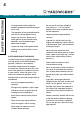
SAFETY DEFINITIONS The purpose of safety symbols is to attract your attention to possible dangers. The safety symbols, and their explanations, deserve your careful attention and understanding. The safety warnings do not by themselves eliminate any danger. The instructions or warnings they give are not substitutes for proper accident prevention measures. allow adults to operate the equipment without proper instruction. –– Thrown objects can cause serious injury.
Safety Instructions model no. 060-1314-4 | contact us: 1.866.523.5218 –– Let engine and machine adjust to outdoor temperatures before starting to clear snow. –– The operation of any powered machine can result in foreign objects being thrown into the eyes. Always wear safety glasses or eye shields during operation, or while performing an adjustment or repair. –– Inspect the auger and impeller before starting to ensure that there is no ice build up. –– Do not over fill fuel tank.
OPERATION –– Do not put hands or feet near or under rotating parts. Keep clear of the discharge opening at all times. –– Exercise extreme caution when operating on or crossing gravel drives, walks, or roads. Stay alert for hidden hazards or traffic. –– –– –– –– After striking a foreign object, stop the engine, remove the spark plug, thoroughly inspect the snowblower for any damage, and repair the damage before restarting and operating the snowblower.
Safety Instructions model no. 060-1314-4 | contact us: 1.866.523.5218 –– –– –– Replace worn or damaged parts for safety. Use only genuine replacement parts and accessories. This snowblower is not intended for use by persons (including children) with reduced physical, sensory or mental capabilities, or lack of experience and knowledge, unless they have been given supervision or instruction concerning use of the appliance by a person responsible for their safety.
Some of the following symbols may be used on this product. Please study them and learn their meaning. Proper interpretation of these symbols will allow you to more safely operate the product. Symbol Meaning Read Operator’s Manual. To reduce the risk of injury, user must read and understand operator’s manual before using this product. Eye and Ear Protection.
Safety Symbols model no. 060-1314-4 | contact us: 1.866.523.5218 Symbol Meaning Thrown Objects. This machine may pick up and throw objects which can cause serious personal injury. Always Use Chute Tool. Never use your hands to clear a clogged chute assembly. Shut OFF engine and remain behind handles until all moving parts have stopped before unclogging. Hot Surface. To reduce the risk of injury or damage, avoid contact with any hot surface. Risk of Fire.
OPERATION SYMBOLS 9 Some of the following symbols may be used on this product. Please study them and learn their meaning. Proper interpretation of these symbols will allow you to more safely operate the product. Symbol Meaning Engine Start. Follow steps to start engine. Check Oil Level. Recommended oil is 0W-30. The engine can be seriously damaged without oil. Always check the oil level before using. The machine must be resting firmly on level ground when checking. Check Fuel Level.
Operation Symbols model no. 060-1314-4 | contact us: 1.866.523.5218 Symbol Meaning Cold Prime. To start a cold engine, prime 3-5 times. Warm Prime. To start a warm engine, DO NOT prime. Recoil Start. Pull the recoil starter grip to start manually. Choke: OFF. When the engine starts, move the choke to run position. Stop. Follow steps to stop. Fuel Valve: OFF. Move the fuel valve lever to the OFF position. Remove Engine Key. Remove the engine key. Engine Start.
model no. 060-1314-4 | contact us: 1.866.523.5218 Stages 2 Speed Control 6 forward/2 reverse Clearing Width 24" (61 cm) Clearing Depth 23" (58.4 cm) Impeller Diameter 12" (30.5 cm) Wheel Diameter 15" (38 cm) Auger Diameter 14" (35.6 cm) ENGINE Brand Champion Power Equipment Displacement 224 cc Engine Model R225S Start Type Electric, Recoil OIL Oil Capacity 16.9 fl. oz. (0.
model no. 060-1314-4 | contact us: 1.866.523.5218 Specifications SNOWBLOWER A. B. C. D. E. F. G. H. I. J. K. L. M. N. O. P. Q. R. S. Discharge Chute Rotation Lever Auger Control Lever Speed Control Lever Shear Pin Storage Discharge Chute Deflector Lever Self-drive Control Lever Grip Heat Warmer Switch Clean-out Tool Upper Handle Discharge Chute Deflector Discharge Chute Auger Shave Plate Skid Shoes Auger Housing Wheels Lower Handle Handle Locking Knobs Lights ENGINE A. B. C. D. E. F. G. H. I. J.
Specifications model no. 060-1314-4 | contact us: 1.866.523.
ASSEMBLY 14 model no. 060-1314-4 | contact us: 1.866.523.5218 UNPACKING 1. Set the shipping carton on a solid, flat surface. Assembly 2. Remove everything loose from the carton. 3. Cut down the bottom carton to allow a flat surface area to install the assembly parts without scratching parts or cutting tires. 4. Now you are ready for assembly. TOOLS REQUIRED Part Size Wrench (included) 13,16 ADDITIONAL PARTS Part Part Qty.
model no. 060-1314-4 | contact us: 1.866.523.5218 HANDLE 1. Attach the lower handle (1-1) onto the unit body with 4 self-tapping bolts (1-2) using included tool or your own 13mm wrench (Fig. 1). Assembly 1-1 1-2 Figure 1 2-1 2-2 2. Connect the upper and lower handle with bolts (2-1), washers (2-2) and locking knobs (2-3) (Fig. 2). The top handle can adjust to 4 positions. You can come back later and adjust to a more comfortable height. 2-3 Figure 2 3.
Assembly model no. 060-1314-4 | contact us: 1.866.523.5218 4. Put the snow discharge chute cable wire form on the snow discharge support using the washer (4-1) and nut (4-2). Securely tighten the assembly (Fig. 4) using included tool or your own 16mm wrench. This will be the guide that channels all the cables over the engine from the chute area. 4-2 4-1 Figure 4 5-1 5-2 Figure 5 5. Route the cables through the support rod wire form (5-1) and cord clamp (5-2) on the lower handle.
model no. 060-1314-4 | contact us: 1.866.523.5218 Capacity of engine oil: 16.9 fl. oz. (0.5 L) Use 0W-30, but in some cases, depending on weather, 5W-30 will work. See chart for oil type recommendations. Weather will affect engine oil and engine performance. Change the type of engine oil used based on weather conditions to suit the engine needs. Recommended Engine Oil Type 0W-30 °F -20 °C -28.9 0 -17.8 / 5W-30 20 -6.7 40 4.
model no. 060-1314-4 | contact us: 1.866.523.5218 ADD FUEL Fuel tank capacity: 88 fl. oz. (2.6 L) Assembly Use clean, fresh, regular unleaded gasoline with a minimum octane rating of 85 and an ethanol content of less than 10% by volume. SAFE HANDLING OF GASOLINE To avoid severe injury or property damage use high levels of care while handling gasoline. Gasoline is an extremely flammable substance and the vapours are explosive.
model no. 060-1314-4 | contact us: 1.866.523.5218 9. Never store the machine or fuel container inside where there is an open flame, spark or pilot light (e.g., furnace, water heater, space heater, clothes dryer etc.). 10. Allow machine to cool at least 5 minutes before storing. 12. If possible, remove gas-powered equipment from the truck or trailer and refuel it on the ground.
OPERATION 20 model no. 060-1314-4 | contact us: 1.866.523.5218 GENERAL SAFETY operation 1. Read the operating and service instruction manual carefully. Be thoroughly familiar with the controls and the proper use of the equipment. Know how to stop the unit and disengage the controls quickly. 2. Never allow children under 16 years old to operate the equipment. Never allow adults to operate the equipment without proper instruction. 3. Thrown objects can cause serious injury.
model no. 060-1314-4 | contact us: 1.866.523.5218 OPERATION 2. Exercise extreme caution when operating on or crossing gravel drives, walks, or roads. Stay alert for hidden hazards or traffic. 3. After striking a foreign object, stop the engine, remove the spark plug, thoroughly inspect the snowblower for any damage, and repair the damage before restarting and operating the snowblower. 4. If the unit should start to vibrate abnormally, stop the engine and check immediately for the cause.
model no. 060-1314-4 | contact us: 1.866.523.5218 18. Take all possible precautions when leaving the machine unattended. Stop the engine and remove the safety key. operation 19. Keep all nuts, bolts and screws tight to be sure the equipment is in safe working condition. 20. Replace worn or damaged parts for safety. Use only genuine replacement parts and accessories. 21.
model no. 060-1314-4 | contact us: 1.866.523.5218 BEFORE OPERATION –– Look around and underneath the engine for signs of oil or gasoline leaks. –– Remove any excessive dirt or debris, especially around the muffler and recoil starter. –– Look for signs of damage. –– Check that all shields and covers are in place, and all nuts, bolts, and screws are tightened. CHECK THE ENGINE: 1. There is no fuel or oil in the engine. Fill with fuel and add 0W-30 prior to first use. 2.
STARTING THE ENGINE 24 STARTING THE ENGINE model no. 060-1314-4 | contact us: 1.866.523.5218 1. Make sure the engine key (safety lock out) is inserted into the keyhole. 2. To start a cold engine: (Fig. 10). 10-1 FULL SPEED 10-2 CHOKE RUN FUEL OFF FUEL ON 10-3 Figure 10 2a. Move the throttle lever (10-1) to full speed. 2b. Move the choke lever (10-2) to the choke position. 2c. Move the fuel shut-off lever (10-3) to the ON position. 2d. Prime 3-5 times. 2e.
4. Stand back and to the right of the unit, pull the starter grip lightly until you feel resistance then pull briskly. Return the starter grip gently (Fig. 12). Figure 12 5. Alternatively, for electric start, plug in the supplied electrical cord into the starter. Press the electric start button and make sure that the main supply voltage is 120 V~ 60 Hz (Fig. 13).
STARTING THE ENGINE model no. 060-1314-4 | contact us: 1.866.523.5218 OPERATION AT HIGH ALTITUDE The density of air at high altitude is lower than at sea level. Engine power is reduced as the air mass and air-fuel ratio decrease. Engine power will be reduced approximately 3 ½% for every 1000' (304 m) of elevation above sea level. This is a natural trend and cannot be changed by adjusting the engine.
CONTROLS 27 model no. 060-1314-4 | contact us: 1.866.523.5218 SELF-DRIVE CONTROL LEVER. Located on the left-side (from behind the snowblower). Releasing the self-drive control lever causes the machine to stop moving. SPEED CONTROL LEVER. Forward speeds range from slowest position 1 to fastest position 6. Reverse speeds range from slowest position R1 to fastest position R2. CONTROLS When the snowblower has been put into gear, pushing this lever towards the handle engages the wheels.
model no. 060-1314-4 | contact us: 1.866.523.5218 AUGER CONTROL LEVER. Located on the right side (from behind the snowblower). Pushing this lever towards the handle causes the auger and impeller to activate. CONTROLS Releasing the auger control lever causes the auger to stop moving. Discharge chute deflector lever controls the deflector up or down. Discharge chute rotation lever controls the chute either left or right.
model no. 060-1314-4 | contact us: 1.866.523.5218 ADJUSTING THE SELF-PROPELLED DRIVE SYSTEM: 1. Release the self-drive control lever to bring the snowblower to a stop. 2. Move the speed-control lever to the gear (either forward or reverse) that you require. CONTROLS 3. Press the self-drive control lever to engage the drive system. Smart Steer technology enables effortless power steering on your snowblower.
model no. 060-1314-4 | contact us: 1.866.523.5218 CHANGE DISCHARGE DIRECTION: 1. Move the discharge chute rotation lever either left or right. CONTROLS CHANGE DISCHARGE HEIGHT: 1. Discharge chute deflector lever controls the deflector up or down. ADJUSTING THE SNOW SHOES –– Tilt the snowblower auger back and place a spacer under the shave plate below the augers that is the height that you want the shave plate to ride above the ground.
MAINTENANCE 31 model no. 060-1314-4 | contact us: 1.866.523.5218 No parts inside the gearbox are to be lubricated. All bearings and bushings are permanently lubricated and require no maintenance. Lubricating these parts will only result in the grease getting on to the friction wheel and disc drive plate, which could damage the rubber clad friction wheel. LONG-TERM STORAGE Never store the machine with gasoline in the fuel tank in a confined area with bad ventilation.
model no. 060-1314-4 | contact us: 1.866.523.5218 REGULAR SERVICE PERIODS maintenance Perform at every indicated month or operating hour interval, whichever comes first. Item Engine Oil Spark Plug Service Each Use Every month or 20 hrs. Every 3 months or 50 hrs. Every 6 months or 100 hrs. Every year or 150 hrs.
model no. 060-1314-4 | contact us: 1.866.523.
3 2 4 5 8 9 6 1, Figure E 2 6 7, Figure D 10 23 12 11 4 Figure A 5 3 13, Figure F 14 12 14 16 24, Figure B 21 22 17 18 19 17 15 14 12 16 20, Figure G FIG. A – SNOWBLOWER PARTS DIAGRAM 34 model no. 060-1314-4 | contact us: 1.866.523.
Item Part Number Description Qty. 1 Figure E Auger Assembly 1 2 30133020025000 Flange Triangle Self-tapping Screw, M10 × 18, White Zinc 4 3 23012000105000A Quick Clip, T=1 mm, Black 2 4 2301300006A Wheel Shaft Washer, T=2, 16.
1 2 3 4 5 6 7 8 9 10 12 11 14 13 15 16 19 17 18 17 20, FIG. B – ENGINE DIAGRAM 36 model no. 060-1314-4 | contact us: 1.866.523.
Item Part Number Description Qty. 1 30913040085000 Hexagon Bolt, M8 × 35, Blue White Zinc 1 2 A26800800202 Spring Washer, 8, Black Zinc 1 3 23032000335000A Thickened Big Washer, Ø8.2 × Ø30 × 3.7, White Zinc 1 4 31013010065000 Flat Key, B4.7 × 4.7 × 70, Black 1 5 23033000415000A Small Belt Pulley, Ø69.5 × 48, Black 1 6 23034000525000A Small Synchronous Pulley Cover, 19 × 50 × 5.
80 20 106 81 78 21 85 42 22 25 103 79 23 30 80 83 82 84 29 38 36 89 81 24 32 33 34 85 43 80 102 78 26 27 78 104 30 27 28 42 33 105 22 31 32 102 43 5 85 28 98 103 39 102 18 19 37 9 60 31 35 44 14 99 64 47 46 50 82 37 101 83 45 100 91 9 2 34 1 8 97 87 48 49 67 41 57 66 51 15 40 65 90 16 20 92 84 34 38 39 61 36 107 6 17 6 10 94 96 7 86 88 61 20 52 11 95 93 13 12 69 62 95 5 76 71 20 68 54 63 72
Item Part Number Description Qty. 1 11310-Z1S0110-0B00 Crankcase Subassembly 1 2 11011-Z1S0210-0000 Oil Drain Tube, 165 × 16, Blue White Zinc 1 3 90408-Z010110-0000 Washer, Ø10 × Ø15.8 × 1.5 1 4 11007-Z010110-0000 Drain Plug Bolt, M10 × 1.25 × 15, Blue White Zinc 1 5 90682-Z1S0110-0001 Oil Seal, Ø25 × Ø41.
FIG. C – PARTS LIST – ENGINE DETAIL model no. 060-1314-4 | contact us: 1.866.523.5218 Item Part Number Description Qty.
Item Part Number Description Qty. 69 19304-Z1S0110-0000 Cylinder Body Shroud, Blue White Zinc 1 70 19340-Z050120-0000 Lower Shield, Blue White Zinc 1 71 90204-Z520110-0000 Stud, M6 × 92.
FIG. C – PARTS LIST – ENGINE DETAIL model no. 060-1314-4 | contact us: 1.866.523.5218 Item Part Number Description Qty.
model no. 060-1314-4 | contact us: 1.866.523.
1 2 3 6 4 5 7 8 9 10 15 12 32 16 11 19 18 17 37 18 13 14 33 34 18 Figure D 31 35 50 38 36 48 39 40 1737 16 15 12 43 44 45 13 42 19 14 41 27 29 18 26 28 49 21 25 18 23 24 21 22 20 18 30 46 12 19 14 13 12 46 47 FIG. D – DRIVETRAIN DIAGRAM 44 model no. 060-1314-4 | contact us: 1.866.523.
Item Part Number Description Qty. 1 23033000385000A Housing Connecting Shaft, 10 × 320, Black 1 2 30313090015000 Hexagon Locking Nut, M12, White Zinc 1 3 30512040015000 Flat Washer, 12, d14 × D24 × t2.6, Blue White Zinc 1 4 23038000125000C Extension Spring, Ø8.5 × 44.9, 65Mn 1 5 23035000395000A Friction Disc Bracket, T=2.5, 279 × 220.
FIG. D – PARTS LIST – DRIVETRAIN model no. 060-1314-4 | contact us: 1.866.523.5218 Item Part Number Description Qty. 34 23013000195000A Wheel Shaft Bushing Assembly, 25.4 × 195, 45# 1 35 23013000105000A GT Differential Mechanism 1 36 2303300037A Wheel Shaft, 25.
model no. 060-1314-4 | contact us: 1.866.523.
1 2 3 4 56 7 8 9 5 7 10 9 12 22 23 21 Figure E 11 5 6 7 4 3 2 1 14 15 18 19 13 43 42 20 24 27 42 43 25 19 18 3 37 3916 38 35 3334 32 31 16 2930 26 28 36 40 16 17 41 FIG. E – AUGER DIAGRAM 48 model no. 060-1314-4 | contact us: 1.866.523.
Item Part Number Description Qty. 1 30913070185000 Hexagon Flange Bolt, M8 × 20, Blue White Zinc 6 2 23091000060001A Spherical Bearing Sheath, Black 2 3 30693010055000 Outer Spherical Ball Bearing, 47 × 20 × 31 3 4 2309400003A Spherical Bearing Support, SMF5040 2 5 23093000195000B B Pin, White Zinc 4 6 23053000245000A Auger Connecting Shaft, 100 × 25.4, Black 2 7 23053000055000A Shear Pin, 8 × 42.
FIG. E – PARTS LIST – AUGER model no. 060-1314-4 | contact us: 1.866.523.5218 Item Part Number Description Qty. 34 23032000335000A Thickened Big Washer, Ø8.2 × Ø30 × 3.7, White Zinc 1 35 30913040115000 Hexagon Bolt, M8 × 25, Blue White Zinc 1 36 30933010015000 Small Carriage Bolt, M8 × 40, Blue White Zinc 1 37 23034000555000A Sheath, Large Tension Wheel, 20 × 18.3 1 38 23032000105000C Large Tension Pulley, Ø66.5 × 36.2,1.
model no. 060-1314-4 | contact us: 1.866.523.
1 3 4 5 2 18 2 6 9 7 8 16 17 16 17 10 11 12 13 14 15 19 FIG. F – CHUTE DIAGRAM 52 model no. 060-1314-4 | contact us: 1.866.523.
Item Part Number Description Qty. 1 23075000210027A Chute Assembly, 453 × 167 × 137, Cool Gray 1 2 A26809000301 7 3 23076000105000A Chute Rubber Self-plugging Rivet, 4 × 10 × 8.08 1 4 23092000205000A Hinge, 85 × 22, White Zinc 1 5 23075000020027A Discharge Chute Deflector 1 6 23068000185000A Pressing Spring, Ø1.
29 31 32 18 36 37 38 39 40 33 34 35 43 41 42 44 45 34 33 30 18 2 35 3 38 39 44 4 6 7 43 1 11 Figure G 31 5 1 10 5 8 10 1 13 21 11 12 18 17 16 23 22 12 25 28 9 14 11 14 11 15 47 46 26 12 20 19 18 17 16 11 21 25 27 23 22 12 26 21 25 24 23 22 12 FIG. G – HANDLE ASSEMBLY DIAGRAM 54 model no. 060-1314-4 | contact us: 1.866.523.
Item Part Number Description Qty. 1 30113010265000 Self-tapping Screw, ST4.2 × 8, Black Zinc 11 2 23041000090243A Right Decorative Ring, ABS750SW 1 3 23041000060027A Light Panel 1 4 2308900011A LED Light Assembly, Right 1 5 30113010255000 Self-tapping Screw, ST4.
FIG. G – PARTS LIST – HANDLE model no. 060-1314-4 | contact us: 1.866.523.5218 Item Part Number Description Qty. 34 23066000145000A Trigger Isolation Gasket, 16 × 13.2 × 19.
model no. 060-1314-4 | contact us: 1.866.523.
R WHITE RED W R Plug BLACK B R AC start cable B Generator R Engine B B Alternating current W B Power outlet wire B R B Left LED lamp ass'y Panel wiring harness R Right LED lamp ass'y Heated handle B R Heated handle B R R R Heated hand grip switch FIG. W – WIRING DIAGRAM 58 model no. 060-1314-4 | contact us: 1.866.523.
model no. 060-1314-4 | contact us: 1.866.523.
TROUBLESHOOTING 60 TROUBLESHOOTING model no. 060-1314-4 | contact us: 1.866.523.5218 PROBLEM Engine fails to start. Engine starts hard or runs poorly. Auger does not rotate. Auger does not stop when the lever is released. Snowblower veers to one side. Snowblower does not drive. POSSIBLE CAUSE REMEDY Engine flooded. Repeat start attempts with throttle choke OFF. Water in fuel. Drain tank and refill with fresh fuel. Other. Check carefully the start procedure according to this manual.
WARRANTY 61 4-YEAR LIMITED WARRANTY For Four YEARS from the date of purchase within Canada, YARDWORKS CANADA will, at its option, repair or replace for the original purchaser, free of charge, any part or parts found to be defective in material or workmanship. THIS WARRANTY DOES NOT COVER: 1. Any part that has become inoperative due to misuse, commercial use, abuse, neglect, accident, improper maintenance, or alteration; 2.
WARRANTY model no. 060-1314-4 | contact us: 1.866.523.5218 ADDITIONAL LIMITATIONS This warranty applies only to the original purchaser and may not be transferred. Neither the retailer nor the manufacturer shall be liable for any other expense, loss or damage, including, without limitation, any indirect, incidental, consequential or exemplary damages arising in connection with the sale, use or inability to use this product.
model no. 060-1314-4 | contact us: 1.866.523.
CHAMPION POWER EQUIPMENT, INC. (CPE), UNITED STATES ENVIRONMENT PROTECTION AGENCY (U.S. EPA) EMISSION CONTROL SYSTEM WARRANTY Your Champion Power Equipment (CPE) engine complies with U.S. EPA emissions regulations. YOUR WARRANTY RIGHTS AND OBLIGATIONS: The US EPA and CPE are pleased to explain the Federal Emission Control Systems Warranty on your 2019 small off-road engine (SORE) and engine powered equipment. New engines and equipment must be designed, built and equipped, at the time of sale, to meet U.S.
EMISSION CONTROL SYSTEM WARRANTY The following are specific provisions relative to your Emission Control System (ECS) Warranty Coverage. 1. APPLICABILITY: This warranty shall apply to 1997 and later model year small off-road engines (SORE). The ECS Warranty Period shall begin on the date the new engine or equipment is delivered to its original, end-use purchaser, and shall continue for 24 consecutive months thereafter. 2.
3i. Any CPE Authorized and approved emission-related replacement part may be used in the performance of any ECS Warranty maintenance or repair and will be provided without charge to the owner. Such use shall not reduce CPE’s warranty obligation. 3j. Unapproved add-on or modified parts may not be used to modify or repair a CPE engine. Such use voids this ECS Warranty and shall be sufficient grounds for disallowing an ECS Warranty claim.