Electric Snow Thrower 60-3982-0 Owner's Manual TOLL-FREE HELPLINE: 1 866 523-5218 IMPORTANT: Read all safety rules and instructions carefully before using this product.
TABLE OF CONTENTS Specifications . . . . . . . . . . . . . .. . . . . . . . . . . . . . . . . . . . . . . . . . . . . . . . . . . . . . . . . . . . . . . . . . . . . . . . . . . . . . . . . 2 General Safety Rules. . . . . . . . . . . . . . . . . . . . . . . . . . . . . . . . . . . . . . . . . . . . . . . . . . . . . . . . . . . . . . . . . . . . . . 3-6 Assembly Instructions . .. . . . . . . . . . . . . . . . . . . . . . . . . . . . . . . . . . . . . . . . . . . . . . . . . . . . . . . . . . . . . . . . . .
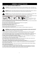
GENERAL SAFETY RULES READ ALL INSTRUCTIONS CAREFULLY! CAUTION: Failure to obey safety warnings may result in property damage or injury to the operator or to others. Follow the safety precautions in order to reduce the risk of fire, electric shock, and personal injury. WARNING: Failure to obey safety warnings may result in injury to the operator and to others. Follow the safety precautions in order to reduce the risk of fire, electric shock, and personal injury.
GENERAL SAFETY RULES Electrical Information WARNING: To avoid electrical hazards, fire hazards, or damage to the tool, use proper circuit protection. The Snow Thrower is wired at the factory for 120 V operation. Connect to a 120 V, 15 A circuit and use a 15 A time delayed fuse or circuit breaker. To avoid shock or fire when the power cord is worn, cut, or damaged in any way, replace it immediately. 1 This Snow Thrower has a 3-prong plug that is intended for use on a circuit Fig.
GENERAL SAFETY RULES FOLLOW THESE RULES WHILE OPERATING THE SNOW THROWER • Walk. Do not run. • Verify that the Snow Thrower is not in contact with anything before turning it on. • Stay away from the discharge opening at all times. Keep face, hands, and feet away from concealed, moving, or rotating parts. • Be attentive when using the Snow Thrower, and stay alert for holes in the terrain and other hidden hazards or traffic. • Do not use the Snow Thrower on a gravel or crushed rock surface.
GENERAL SAFETY RULES • Use only the manufacturer's original replacement parts and accessories for this Snow Thrower. The use of unauthorized parts or accessories could lead to serious injury to the user or damage the Snow Thrower, and will void the warranty. • Do not use the Snow Thrower in the hand held position. Do not pick up the Snow Thrower while it is plugged and running. The Snow Thrower is designed to travel along the ground. • Verify that the Snow Thrower is secure while transporting.
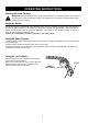
ASSEMBLY Assembling the Handle (Fig. 1) 1. Remove any packing material that may have been inserted between the upper and lower handles for shipping purposes. 2. Align the holes (4) on the upper handle (1) with the holes on the middle handle (2). Insert the bolts (5), and use the wing nuts (6) to tighten them. 3. Align the holes (7) on the middle handle (2) and the lower handle (3). Insert the bolts (5), and tighten them using the wing nuts (6) provided. Assembling the Discharge Directional Control (Fig.
Diagram and Location of Parts Diagram and Location of Parts (Fig. 2) Fig.
OPERATING INSTRUCTIONS Starting the Snow Thrower WARNING: Avoid accidental start-ups. Verify that the operator is in the starting position when using the snow thrower. In order to avoid serious injury, the operator and unit must be in a stable position when starting the Snow Thrower. Using the Switch This Snow Thrower is equipped with a special safety switch. In order to operate the switch, insert one finger into the opening, and push the lever out so that it can be grasped along with the upper handle.
OPERATING INSTRUCTIONS Adjusting the Direction of Discharge (Fig. 3-4) Snow can be discharged to the left, straight ahead, or to the right of the operator. Follow these instructions in order to change the direction of the discharge: 1. Release the switch bar in order to stop the rotor. NOTE: The control stick can revolve 720°. NOTE: From the center position, the discharge directional control turns approximately 360° in either direction (clockwise or counter-clockwise). Do not force it. 2.
MAINTENANCE Servicing Servicing should be performed by a qualified technician. Replacement parts for this Snow Thrower must be identical to the parts that they replace. If repairs are necessary, contact the Toll-Free Helpline, at 1-866-523-5218. Inspecting/Replacing the Drive Belt (Fig. 5-7) When servicing the Snow Thrower, use only the manufacturer's original replacement parts. Inspect the drive belt for wear once per year or every 50 hours of operation, whichever comes first.
MAINTENANCE Impellor replacement 1 2 3 spring 1. Remove the nut from the left hand side of the impellor shaft. 4 2. Remove the 10 screws from the side cover. 5 3. Be sure not to lose the 2 springs. 6 spacer washer washer and screw 4. Remove the washer and the screw. 7 5. Remove the nut from the impellor shaft. Remove the 3 screws holding the pulley support plate. 8 7. Remove the pulley and belt. 10 6. Remove the plate and the two spacer washers. 9 8.
MAINTENANCE Impellor replacement 13 14 13. Place the pulley back onto the impellor shaft. 16 15 14. Be sure to route the belt correctly, as shown. 17 15. Replace the 2 spacer washers on the impellor shaft. 18 washer and screw impellor shaft washer and nut 16. Replace the pulley support plate and the 3 retaining screws. 19 17. Replace and tighten the impellor shaft washer and nut. 20 18. Replace the washer and the screw. 21 spring 19.
(Fig. 8) (Fig. 8) Fig.
TROUBLESHOOTING Problem Possible Causes Solutions Then handle is not in position. The carriage bolts are not properly seated Adjust the height of the handle, and verify that the carriage bolts are properly seated. Tighten the knobs. The Snow Thrower does not start. The Snow Thrower is unplugged. Verify that the Snow Thrower is plugged into an electrical outlet. Press and hold the lock-out button, and then lift and hold the trigger switch (see the section entitled Starting the Snow Thrower).
WARRANTY For TWO YEARS from the date of purchase within Canada, YARDWORKS CANADA will, at its option, repair or replace for the original purchaser, free or charge, any part or parts found to be defective in material or workmanship. This warranty does not cover: 1. Any part which has become inoperative due to misuse, commercial use, abuse, neglect, accident, improper maintenance or alteration; or 2. The unit, if it has not been operated and/or maintained in accordance with the owner's manual;or 3.
PARTS LIST 17
PARTS LIST No 1 2 3 4 5 6 7 8 9 10 11 12 13 14 15 16 17 18 19 20 21 22 23 24 25 26 27 28 29 30 31 32 33 34 35 36 Model num. 3118099 3220436 3410835-4 3330299-3 3330399-3 3290135 3220199 3290799 3290699 3411799-1 3411799C 3330398 3220299 Description Upper handle assembly Screw Knob Middle handle Down handle Clip pin Screw Shrapnel Gasket Left wheel assy.