Commercial 1000VDC String Inverter Solectria PVI 25TL-480-R Installation and Operation Guide Model: PVI 25TL-480-R
Installation and Operation Guide SOLECTRIA PVI 25TL-480-R 1. 2. 3. 4. 5. 6. Important Safety Instructions ......................................................................................................................................... 4 1.1 Hazard Symbols ....................................................................................................................................................... 4 1.2 Symbols on Labels .............................................................
Installation and Operation Guide SOLECTRIA PVI 25TL-480-R 7. 8. Maintenance and Decommissioning of Inverters ......................................................................................................... 84 7.1 Product Maintenance ........................................................................................................................................... 84 7.2 Uninstall the Inverter ..............................................................................................
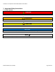
Installation and Operation Guide SOLECTRIA PVI 25TL-480-R 1. Important Safety Instructions 1.1 Hazard Symbols DANGER Indicates a hazardous situation, which, if not avoided, will result in death or serious injury. WARNING Indicates a hazardous situation, which, if not avoided, could result in death or serious injury. CAUTION Indicates a hazardous situation, which, if not avoided, could result in minor or moderate injury.
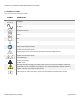
Installation and Operation Guide SOLECTRIA PVI 25TL-480-R 1.2 Symbols on Labels Table 1-1 Explanation of Symbols on Labels SYMBOL DESCRIPTION DC Signal AC Signal Equipment Ground Phase Off On Refer to Operating Instructions Caution: Risk of Electric Shock Do not remove cover until 5 minutes after disconnecting all supply sources Caution: Risk of Electric Shock Timed Discharge Caution: Hot Surface Do Not Touch Warning: Hazardous voltage area under plastic cover. Do not open fuse holders under load.
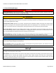
Installation and Operation Guide SOLECTRIA PVI 25TL-480-R 1.3 General Safety Messages DANGER Electric Shock Hazard: Components with hazardous voltage and energy will electrocute operator. Operator shall avoid touching live components with hazardous voltage and energy. WARNING Unqualified Operator Hazard: Operator may cause a hazardous situation by making incorrect installation or wiring connections.
Installation and Operation Guide SOLECTRIA PVI 25TL-480-R SAVE THESE INSTRUCTIONS This manual contains important instructions for model: PVI 25TL-480-R DOCR-071030-A (11/17/2020) Page 7 of 101
Installation and Operation Guide SOLECTRIA PVI 25TL-480-R 1.4 Status Panel The Status Panel consists of four LED icons that provide useful information to the user regarding the current state of the inverter. The Status Panel is shown in Figure 1-1 and the icon symbols are defined in Table 1-2.
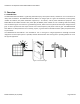
Installation and Operation Guide SOLECTRIA PVI 25TL-480-R 2. Overview 2.1 Intended Use The SOLECTRIA PVI 25TL-480-R is a grid-tied, photovoltaic (PV), three-phase inverter, suitable for use in commercial or utility-scale installations. The SOLECTRIA PVI 25TL-480-R is an integral part of a typical PV installation, which typically includes PV modules, DC power distribution equipment, a PV inverter, and AC power distribution equipment.
Installation and Operation Guide SOLECTRIA PVI 25TL-480-R 2.2 Inverter Features CONVERSION TECHNOLOGY HIGH EFFICIENCY GRID ADAPTABILITY CONNECTIVITY USER INTERFACE (UI) MULTICHANNEL MPPT CONFIGURATION PROTECTIVE ENCLOSURE EASY INTEGRATION RAPID SHUTDOWN READY 3 - Level Max 98.5%, CEC 98% Supports multiple grid trip setpoints Pre-set grid setpoints: IEEE 1547, CA Rule 21, ISO-NE Adjustable reactive power Adjustable power factor (PF) ±0.
Installation and Operation Guide SOLECTRIA PVI 25TL-480-R 2.4 Communication Overview The SOLECTRIA PVI 25TL-480-R utilizes an advanced communication platform that can be accessed over Wi-Fi using a smart device via the FOMlink wireless antenna device. This provides the user with a single point of access to all inverters within a network, without needing to travel the site to interact with individual inverters.
Installation and Operation Guide SOLECTRIA PVI 25TL-480-R 13.1in(333.0mm) 3.3in(85.0mm) 12.1in(308.0mm) 2.4in(60.0mm) 11.1in(283.0mm) 1.4in (35.0mm) 4.4in (111.0mm) DC INPUT COMM. PORT LINKIT AC OUTPUT For more details please see the user manual. WARNING: High touch current . Earth connection essential before connecting supply.
Installation and Operation Guide SOLECTRIA PVI 25TL-480-R ① ② ③ ④ ⑤ ⑥ DC Input fuse holder/terminal (positive) DC Input terminal (negative) Communication board Internal ground terminal RSD transmitter AC output terminal block 2.6 Schematic Diagram and Circuit Design The basic electrical schematic diagram of SOLECTRIA PVI 25TL-480-R inverters is shown in Figure 2-4.
Installation and Operation Guide SOLECTRIA PVI 25TL-480-R Figure 2-5 Example Power Head Labels for SOLECTRIA PVI 25TL 2.8 Unpacking The SOLECTRIA PVI 25TL-480-R inverter ships in one box. Prior to installation, be sure to store the packaged inverter(s) out of the elements. The inverter enclosures are not NEMA Type 4X rated until fully installed. Storage temperatures are -40°F to +158°F (-40°C to +70°C). Open the boxes carefully to avoid damaging the contents.
Installation and Operation Guide SOLECTRIA PVI 25TL-480-R Figure 2-6 Shipment Box Contents DOCR-071030-A (11/17/2020) Page 15 of 101
Installation and Operation Guide SOLECTRIA PVI 25TL-480-R Table 2-1 Shipment Box Contents IDENTIFIER 1 2 3 4 3.
Installation and Operation Guide SOLECTRIA PVI 25TL-480-R PRE-INSTALLATION CHECKLIST Check that the inverter environmental specifications (protection degree, operating temperature range, humidity and altitude, etc.) meet the requirements of the specific project location. Make sure that the electric utility grid voltage is within range for the grid standard chosen. Ensure that the local electric utility grid authority has granted permission to connect to the grid.
Installation and Operation Guide SOLECTRIA PVI 25TL-480-R Each subsection begins with general requirements and guidelines which must be considered when designing a system and planning the installation. Each sub-section is concluded with detailed systematic instructions to install the SOLECTRIA PVI 25TL-480-R. 3.1 Installation Sequence Overview CAUTION Lifting Heavy Object Hazard: Proper lifting techniques must be used in order to avoid injuries. The Power Head weighs 48.5 pounds (22 kg). 1.
Installation and Operation Guide SOLECTRIA PVI 25TL-480-R Maintain NEMA Type 4X Rating: It is the responsibility of the installer to maintain the NEMA Type 4X rating of the enclosure. Failure to maintain the NEMA Type 4X rating will void the warranty. NOTICE! Improper Installation Will Void Warranty: Never install the inverter in areas that are prone to flooding, standing water, or prolonged snow coverage. It is important to ensure the cooling fans and exhausts remain clear from obstructions at all times.
Installation and Operation Guide SOLECTRIA PVI 25TL-480-R 2. The bottom edge of the Wire-Box must remain horizontal (perpendicular to a plumb line). No side-to-side tilting is permitted. 3. Do not mount the inverter leaning forward. 4. Do not mount the inverter at an angle lower than 15° from horizontal. 3.2.3 Inverter Dimensions The dimensions of the SOLECTRIA PVI 25TL-480-R are shown in Figure 3-2. Figure 3-2 Inverter Dimensions 3.2.
Installation and Operation Guide SOLECTRIA PVI 25TL-480-R Figure 3-3 Inverter Minimum Spacing and Clearance Area DOCR-071030-A (11/17/2020) Page 21 of 101
Installation and Operation Guide SOLECTRIA PVI 25TL-480-R 3.2.5 Mounting A mounting bracket, shown in Figure 3-5, is provided with each SOLECTRIA PVI 25TL-480-R. Direct mounting to any surface without using the provided mounting bracket is not permitted. The mounting bracket must be securely attached to a structurally sound, flat surface. Acceptable surfaces include U-channel metal racking (such as Unistrut), concrete, and other non-flammable surfaces.
Installation and Operation Guide SOLECTRIA PVI 25TL-480-R Figure 3-4 Mounting Bracket - Hole Locations DOCR-071030-A (11/17/2020) Page 23 of 101
Installation and Operation Guide SOLECTRIA PVI 25TL-480-R 3.2.6 Mechanical Installation, Method Table 3-1 Tools Required TOOL NO. 2 PHILLIPS HEAD SCREWDRIVER NO. 10 WRENCH NO. 3 PHILLIPS HEAD SCREWDRIVER DESCRIPTION Torque value of 1.6 Nm (14.2 in-lbs) Torque value of 4 Nm (35.4 in-lbs) Torque value of 4 Nm (35.4 in-lbs) 3.2.6.1 Assemble and Install Mounting Bracket The Mounting Bracket is shown in Figure 3-5. 80.0 (3.1in.) 340.0 (13.4in.) 290.0 (11.4in.) Figure 3-5 Mounting Bracket 3.2.6.
Installation and Operation Guide SOLECTRIA PVI 25TL-480-R Figure 3-6 Mount the Power Head to the Bracket 3.2.6.3 Install the Wire-Box NOTICE! It is not advisable to leave the Wire-Box Installed without the Power Head: If it is absolutely necessary to have the Wire-Box installed without the Power Head, keep the bulkhead connector cover on or reinstall the bulkhead connector cover. Remove screws securing the bulkhead connector cover at the top of the wire-box.
Installation and Operation Guide SOLECTRIA PVI 25TL-480-R Save the bulkhead connector cover and screws and attach the cover to the left side of the wire-box after the wire-box is attached to the inverter enclosure. Covers may be required in the future if an inverter or wire-box is to be removed during servicing. Tool required: No.2 Phillips head screwdriver 3.2.6.4 Secure the Power Head to the Wire-Box Secure the wire-box to the main enclosure by using the M6x18 screws (4pcs) to fasten the wire-box.
Installation and Operation Guide SOLECTRIA PVI 25TL-480-R Figure 3-9 Secure the Power Head and Wire-Box to the Bracket 3.2.6.6 Storage of Bulkhead Cover Attach the bulkhead cover shown in Figure 3-7 to the left side of the wire-box as shown in Figure 3-10 for future use. Tool required: No.2 Phillips head screwdriver, torque value of 1.6N.m (14.2in-lbs) Figure 3-10 Attach Bulkhead Cover to Wire-Box 3.2.6.
Installation and Operation Guide SOLECTRIA PVI 25TL-480-R Figure 3-11 Location of Anti-Theft Padlock Hole The anti-theft padlock shackle should meet the requirements of the dimensions shown in Figure 3-12. Figure 3-12 Acceptable Dimensions for Anti-Theft Padlock 3.3 Wire-Box 13.1in(333.0mm) 3.3in(85.0mm) 12.1in(308.0mm) 2.4in(60.0mm) 11.1in(283.0mm) 1.4in (35.0mm) 4.4in (111.0mm) DC INPUT LINKIT COMM. PORT AC OUTPUT For more details please see the user manual. WARNING: High touch current .
Installation and Operation Guide SOLECTRIA PVI 25TL-480-R ② ③ ④ ⑤ ⑥ Knock-outs for AC output, (2) 1-1/2 inch Trade Size Knock-out for communication, (4) 3/4 inch Trade Size FOMlink Dongle port Vent External ground connection point (M6) 7 8 10 9 11 12 Figure 3-14 Internal Connection Points within the Wire-Box ⑦ ⑧ ⑨ ⑩ ⑪ ⑫ DC Input fuse holder/terminal (positive) DC Input terminal (negative) Communication board Internal ground terminal RSD transmitter AC output terminal block 3.
Installation and Operation Guide SOLECTRIA PVI 25TL-480-R NOTICE! DC Overload: Exceeding the recommended DC to AC ratio may damage the inverter and will void the warranty. Size strings according to information in this section and all applicable electrical codes. DC/AC Ratio and Current Limits: Both DC to AC ratio and Isc limits must be observed. Failure to meet these requirements may result in damage and will void the warranty.
Installation and Operation Guide SOLECTRIA PVI 25TL-480-R Figure 3-16 Matched (Left) and Mismatched (Right) String Sizes within a Zone or Inverter 3.4.3 DC Connection Specifications The voltage rating of the DC conductors must meet or exceed 1000VDC and be rated at no less than 90°C (194°F). All electrical conductors must meet the requirements of the NEC and local electrical codes.
Installation and Operation Guide SOLECTRIA PVI 25TL-480-R 3.4.4 PV Fuses The SOLECTRIA PVI 25TL-480-R is shipped with factory installed touch-safe fuse holders and 20 A fuses on the positive conductors only. Ensure that the appropriate fuse values are used for the conductors in the PV source circuit, and in accord with NEC 690.9. Yaskawa Solectria does not supply fuses. Use either the 1000VDC Sinofuse RS308 PV fuse series or the Mersen HP10M PV fuse series as replacement fuses if necessary.
Installation and Operation Guide SOLECTRIA PVI 25TL-480-R Figure 3-17 Polarity Check INFO ✔ Wire Ferrules: 10 AWG wire ferrules are intended to preclude the onset of stray/loose wire strands or “bird caging” of the conductor during installation and improve the integrity of the termination. The use of the wire ferrules is not mandatory and shall not void the product warranty if not used. (The ferrules are not provided by Yaskawa Solectria Solar.) 3.4.
Installation and Operation Guide SOLECTRIA PVI 25TL-480-R Use Correct Fuses: Make sure to size the fuses according to NEC requirements. 3.4.6.1 Remove Wire-Box Cover Prior to installation, confirm the Wire-Box to be used is the Wire-Box as shown in Figure 3-18below. Figure 3-18 PVI 25TL-480-R Wire-Box Use a No. 3 Phillips-head screwdriver to remove the four (4) screws from the cover of the Wire Box as shown in Figure 3-19.
Installation and Operation Guide SOLECTRIA PVI 25TL-480-R thread damage, and after screws are fully engaged torque to 35.4 in-lbs (4N.m). 3.4.6.2 1-1/2 inch knockouts Remove the factory installed liquid-tight hole plugs from the DC knockout holes in the Wire-Box and install 1-1/2 inch Trade Size conduit and conduit fittings. If the use of smaller conduit is desired, use proper weather-tight reducing bushings to ensure the Wire-Box maintains its NEMA 4X rating.
Installation and Operation Guide SOLECTRIA PVI 25TL-480-R 3.5.1 Transformer Configurations CAUTION Improper Transformer Configuration: Inverter will not run and may have hazardous current. Connect transformer in specified configurations only (see Figure 3-20). NOTICE! 480 VAC, 60Hz, Grid Grounded Wye ONLY: The inverter is only rated for 480 VAC, 60Hz, 3-Phase grounded Wye. Installing the inverter on any other electrical grid will damage the inverter and void the warranty.
Installation and Operation Guide SOLECTRIA PVI 25TL-480-R Figure 3-21 Transformer Configurations NOT Permitted Transformer short-circuit impedance (Z%) should be less than 6%. Transformer VA rating must be at least 100% of the sum of the connected inverter VA ratings. It is recommended that the transformer VA rating be selected based on IEEE C57.159-2016 Guide on Transformers for application in Distributed Photovoltaic (DPV) Power Generation Systems.
Installation and Operation Guide SOLECTRIA PVI 25TL-480-R With longer wire runs, the use of larger conductors than those required by the NEC can help reduce voltage drop and increase overall system efficiency. The recommended maximum voltage drop from the Inverter to the Point of Common Coupling (the grid) is 2% at full load and including conductor temperature considerations.
Installation and Operation Guide SOLECTRIA PVI 25TL-480-R 3.5.5 Electrical Installation AC, Method DANGER Electric Shock Hazard: Components with hazardous voltage and energy will electrocute operator. Operator shall avoid touching live components with hazardous voltage and energy. Verify the absence of voltage using an appropriately rated multimeter. Always Wear Proper PPE: The proper Personal Protective Equipment (PPE) must be worn while working in proximity to hazardous voltage and energy.
Installation and Operation Guide SOLECTRIA PVI 25TL-480-R 1 2 DC INPUT For more details please see the user manual. WARNING: High touch current . Earth connection essential before connecting supply. Figure 3-22 AC Output and Ground Cable Connection NOTICE! Neutral to Ground Jumper: Do not use a jumper between ground and Neutral if the Neutral conductor is connected. Using a jumper with the Neutral conductor connected may result in damage and will void the warranty.
Installation and Operation Guide SOLECTRIA PVI 25TL-480-R When bonding the inverter/mount to a metallic structure is required, use the OT type terminal to connect the ground conductor to the external bonding point at the bottom of the wire-box. The bonding point is located at the bottom of the Wire-Box as shown in Figure 3-25.
Installation and Operation Guide SOLECTRIA PVI 25TL-480-R Figure 3-26 Communication Board in the Wire-Box 1 2 3 4 5 ① RS485 (Reserved) ② Power port (2pin connector) 1. GND 2. +12V ③ RS485 port (6pin connector) 1. 485_A 2. 485_B 3. 485_GND 4. 485_A 5. 485_B 6. 485_GND ④ Selector Switch (S201): 120Ω terminal resistor switch for communications. 1. ON: Enable the termination resistance 2. OFF: Disable termination resistance ⑤ RJ45(Reserved) Figure 3-27 Communication Board Connections 3.6.
Installation and Operation Guide SOLECTRIA PVI 25TL-480-R A maximum of 32 devices can be connected to this card. When provided with an internet connection, it can send data to an online portal that Yaskawa Solectria Solar can use for troubleshooting and remote diagnostic purposes. As well, customers can opt to purchase access to this portal for easy O&M of their system. It is also used for allowing the connection of a third-party monitoring system.
Installation and Operation Guide SOLECTRIA PVI 25TL-480-R RS485-1 1 485_A 485_B 485_GND 485_A 485_B 485_GND RS485-2 RS485-1 485_A 485_B 485_GND 485_A 485_B 485_GND 2 Figure 3-28 Connection of Single (1) and Multiple Inverters (2) INFO ✔ Shielded Cable: Solar PV inverters create an electrically noisy environment that can disrupt inverter communication. It is important to use shielded cable to ensure communication is not interrupted.
Installation and Operation Guide SOLECTRIA PVI 25TL-480-R Figure 3-29 RS-485 Network Connection If there are multiple inverters in the RS-485 network, the selector switch S201 of the last inverter in the daisy-chain should be in ON position, to have the 120Ω terminal resistor enabled. The selector switch S201 of all other inverters should be in the OFF position to disable the terminal resistor. 3.6.
Installation and Operation Guide SOLECTRIA PVI 25TL-480-R Figure 3-30 Third-Party Data Logger Connection Point on the Ethernet Network Card Figure 3-31 PVI 25TL-480-R Inverters in a RS-485 Daisy Chain to Third-Party DAS When connected to an external DAS, Yaskawa Solectria Solar PVI 25TL-480-R inverters support up to 32 inverters/devices on the RS-485 daisy chain. The Inverter Modbus IDs are configurable from 1 to 128.
Installation and Operation Guide SOLECTRIA PVI 25TL-480-R The shield continuity should be maintained for the entire length of the daisy chain and should only be connected to ground (GND) at the DAS. The shield should not be connected to any of the inverters to prevent any possible grounding loops. It is important to terminate the Modbus (RS-485) daisy chain correctly to minimize any bus noise and reflections.
Installation and Operation Guide SOLECTRIA PVI 25TL-480-R Test the polarity of DC inputs and confirm they are proper. Make sure the open circuit voltage of input strings is less than 1000VDC. 4.2 Startup Steps WARNING Electrical Shock Hazard Installer may come into contact with components that have hazardous voltage and energy potential. Use proper safety equipment when energizing the inverter. Follow these instructions when turning on an inverter. Turn ON the site AC breaker for the inverter.
Installation and Operation Guide SOLECTRIA PVI 25TL-480-R connect it to the access point created by the FOMlink dongle. Choose the Wi-Fi Network named “CPLKXXXXXXX”, where XXXXXX is the serial number (SN) found on the side of the FOMlink Dongle Module. 4. The inverter will need to be initialized on the first start up. a.
Installation and Operation Guide SOLECTRIA PVI 25TL-480-R Figure 4-4 RS-485 Submenu Screens e. Inverter Clock: Set the system clock. f. Change Password: Change current password. When the device screen shows the normal operation status Figure 4-5 and the “POWER” light on the LED panel is illuminated, this means that the grid connection and power generation are successful.
Installation and Operation Guide SOLECTRIA PVI 25TL-480-R Figure 4-6 Fault Information Interface 5. App Interface 5.
Installation and Operation Guide SOLECTRIA PVI 25TL-480-R History Turn ON/OFF Figure 5-2 Sub-menu buttons on bottom of Main Menu screen 5.2.1 Running Data In the Running Data sub-menu you can view the power generation by Day, Month, or Year as shown in Figure 5-3. Figure 5-3 Running Data Sub-menu 5.2.2 Settings To access the Settings sub-menu, use password “1111”. This sub-menu allows access the following sub-menus: Inverter Parameters Read/Write Register Upgrade Firmware 5.2.2.
Installation and Operation Guide SOLECTRIA PVI 25TL-480-R Figure 5-4 Inverter Parameters Sub-menu 5.2.2.
Installation and Operation Guide SOLECTRIA PVI 25TL-480-R 5.2.2.2.
Installation and Operation Guide SOLECTRIA PVI 25TL-480-R Grid Low Voltage Protection Setup range (lower Setup range (lower limit, default & upper limit, default & upper limit) IEEE1547-2018 limit) Rule21 Parameter name Description GridVoltMin1 Threshold value of Level 1 Min. grid voltage {30%, 70%, 100%} {30%, 88%, 100%} VoltMinTripTime1(S) Threshold value of Level 1 Min. grid trip voltage {0, 20.5, 655} GridVoltMin2 Threshold value of Level 2 Min.
Installation and Operation Guide SOLECTRIA PVI 25TL-480-R Grid Over Frequency Protection Setup range (lower Setup range (lower limit, limit, default & default & upper limit) upper limit) Rule21 IEEE1547-2018 Parameter name Description GridF.Max1 Protection threshold value of Level 1 Max. grid {60, 61.2, 66} frequency {60, 60.5, 66} FMaxTripTime1(S) Trip time of Level 1 Max. grid frequency {0, 299.5, 655} GridF.Max2 Protection threshold value of Level 2 Max.
Installation and Operation Guide SOLECTRIA PVI 25TL-480-R FRcovT(S) Recovery time of grid frequency protection VoltMax The upper limit grid voltage of moving average {100%, 110%, filter 135%} {100%, 110%, 135%} MaxTripT The trip time of the upper limit grid voltage of {0, 600, 655} moving average filter {0, 600, 655} VoltMin The lower limit grid voltage of moving average {80%, 88%, 100%} {80%, 87.
Installation and Operation Guide SOLECTRIA PVI 25TL-480-R Power Present 0.0%~100.0% Settable 0 100.00%~135.00% Settable Grid voltage GridV.Max1 Figure 5-8 Over-Voltage Derating Curve Power Present 0.0%~100.0% Settable 0 60.00~72.00Hz Settable GridF.
Installation and Operation Guide SOLECTRIA PVI 25TL-480-R Table 5-2 Active Power Derating Setup Ranges with Lower Limit, Default, and Upper Limit for IEEE 1547-2018 and CA Rule 21 PARAMETER NAME DESCRIPTION SETUP RANGE (LOWER LIMIT, DEFAULT & UPPER LIMIT) IEEE15472018 OvrFrqMin The trigger frequency of OverFrequency derating {60, 60.04,72} {60, 60.04 ,72} OvrFrqMax The end frequency or Rate of Overfrequency derating (Depends on the specific standard) {60,62.532,72} {60, 62.
Installation and Operation Guide SOLECTRIA PVI 25TL-480-R Figure 5-10 ReactivePowerDerating Parameter Screens PF Set - Use this mode to set a static PF value. Note: Change the reactive power by adjusting the PowerFactor. PF(P) Curve – Use this mode to follow the default or user-specified PF curve. Note: The power factor changes according to the power change, as shown in Figure 5-11. Q(U) Curve – Use this mode to follow the default or user-specified Q(U) curve.
Installation and Operation Guide SOLECTRIA PVI 25TL-480-R PF (PFCurveP1,PFCurvePF1) Inductive 1 (P%) -1 Capacitive (PFCurveP2,PFCurvePF2) Figure 5-11 PF(P) Curve Mode Curve Q(%) (QuCurveU2i,QuCurveQ2i) Inductive + _ (QuCurveU1, QuCurveQ1) (QuCurveU1i, QuCurveQ1i) U(V) Capacitive (QuCurveU2,QuCurveQ2) Figure 5-12 Q(U) Curve Mode Curve DOCR-071030-A (11/17/2020) Page 61 of 101
Installation and Operation Guide SOLECTRIA PVI 25TL-480-R Table 5-3 Reactive Power Derating Grid Parameters PARAMETER NAME SETUP RANGE SETUP RANGE (LOWER LIMIT, (LOWER LIMIT, DEFAULT & UPPER DEFAULT & UPPER LIMIT) IEEE1547LIMIT) RULE21 2018 PFSetValue {-1,-0.8},{1},{0.8,1} {-1,-0.8},{-0.95},{0.8,1} Local Power Factor Setting PFpCurveP1 {0%,50%,100%} PF_PCurvePF1 {-1,-0.8},{1},{0.8,1} {-1,-0.8},{1},{0.
Installation and Operation Guide SOLECTRIA PVI 25TL-480-R Figure 5-13 LVRT / HVRT Parameters Voltage N*rated 1 0.9 0.8 0.7 0.6 0.5 0.4 0.3 0.2 0.
Installation and Operation Guide SOLECTRIA PVI 25TL-480-R 1.3 Voltage N*rated 1.25 1 2 3 4 1.2 Through 1.15 5,6,7,8 Trip 1.1 1.
Installation and Operation Guide SOLECTRIA PVI 25TL-480-R {0, 10.5, 655} Threshold value of Low {0%, 70%, 100%} LVRTVoltPara (5,6) voltage ride through (fifth or {0%, 70%, 100%} sixth point) LVRTTimePara(5,6) Time of Level Low voltage ride {0, 10.5, 655} through (fifth or sixth point) {0, 20.5, 655} Threshold value of Low {0%, 88%, 100%} LVRTVoltPara (7,8) voltage ride through(seventh {0%, 88%, 100%} or eighth point) Time of Level Low voltage ride {0, 20.
Installation and Operation Guide SOLECTRIA PVI 25TL-480-R Table 5-5 HVRT Parameters with Setup Range of Lower Limit, Default, and Upper Limit HVRT PARAMETER NAME DESCRIPTION SETUP RANGE SETUP RANGE (LOWER LIMIT, (LOWER LIMIT, DEFAULT & UPPER DEFAULT & UPPER LIMIT) IEEE1547LIMIT) RULE21 2018 Threshold value of high {100%, 125%, 135%} HVRTVoltPara (1,2) voltage ride through (first or {100%, 125%, 135%} {100%, 125%, 135%} second point) {100%, 125%, 135%} Time of Level high voltage {0, 0, 655} HVRTTimePar
Installation and Operation Guide SOLECTRIA PVI 25TL-480-R eighth point) 5.2.2.2.5 Others The Others submenu is for miscellaneous parameters that do not fit in a specific category.
Installation and Operation Guide SOLECTRIA PVI 25TL-480-R Table 5-6 Others Submenu Parameters Setup Ranges with Lower Limit, Default, and Upper Limit Settings PARAMETER NAME DESCRIPTION SETUP RANGE (LOWER LIMIT, DEFAULT & UPPER LIMIT) IEEE15472018 PowerOnDelay Startup delay time (1,5,1200) (1,5,1200) PVStartupVolt PV start-up voltage (200, 330 ,400) (200, 330 ,400) The output power should be slow PVSlowStartPwDelta increased due to the change of PV illumination at the Rule21 standard. {0.
Installation and Operation Guide SOLECTRIA PVI 25TL-480-R GFCIStaticT GFCI static protection time {0,0.2,655} {0,0.2,655} GFCIDynProFactor GFCI dynamic protection factor {0%,100%,200%} {0%,100%,200%} DCIProtection1 maximun DCI value1 {0.1%,0.5%,5%} {0.1%,0.
Installation and Operation Guide SOLECTRIA PVI 25TL-480-R Table 5-7 Enable / Disable Parameters with Lower Limit, Default and Upper Limit Settings (IEEE 1547-2018 and Rule 21) Parameter name Description Setup range (lower limit, default & upper limit) IEEE1547 Setup range (lower limit, default & upper limit) Rule-21 {0, 4, 4} {0, 4, 4} The enabled control parameters group.
Installation and Operation Guide SOLECTRIA PVI 25TL-480-R 2: Local control. (Association register address=0x250E.
Installation and Operation Guide SOLECTRIA PVI 25TL-480-R function Enable} Enable} Gridxx1,2ProEn Disable or Enable the grid protect {Disable,Enable, function and please refer to 5.4.2.3 Enable} setting the grid protect parameters {Disable,Enable, Enable} Gridxx3ProEn Disable or Enable the grid protect {Disable, Enable, function and please refer to 5.4.2.
Installation and Operation Guide SOLECTRIA PVI 25TL-480-R 3:Reserved 4:Reserved 5:Reserved DCI protection1 enable/disable control DCIProtection1En 0: Disable {Disable,Enable, Enable} {Disable,Enable, Enable} {Disable,Disable, Enable} {Disable,Disable, Enable} {Disable,Enable, Enable} {Disable,Enable, Enable} {Disable,Disable, Enable} {Disable,Disable, Enable} 1: Enable DCI protection2 enable/disable control DCIProtection2En 0: Disable 1: Enable Unbalance rate of grid voltage detection enable/dis
Installation and Operation Guide SOLECTRIA PVI 25TL-480-R The AC SPD test enables settings ACSPDDetectEnSet 0: Disable {Disable,Disable, Enable} {Disable,Disable, Enable} {Disable,Disable, Enable} {Disable,Disable, Enable} 1: Enable Operating overvoltage detection enables setting OperationOverVolEn 0: Disable 1: Enable 5.2.2.2.
Installation and Operation Guide SOLECTRIA PVI 25TL-480-R 5.2.3 Fault Recording The Fault Recording Menu can store up to 128 fault records. 5.2.4 History There are 2 submenus in the History menu: Alarm Running Status They are accessed by selecting the History button and then toggling between the two menus as show in Figure 5-18.
Installation and Operation Guide SOLECTRIA PVI 25TL-480-R Figure 5-18 History Submenu 5.2.5 Turn On / Off Manual Turn ON/OFF: Manual Power ON/OFF is required after regulation setting or manual (fault) shut-down. Select the submenu “Turn ON/OFF”. Turn ON: Click “Turn ON” and “OK” to start the inverter, the inverter will start up and operate normally if the startup conditions are met. Otherwise, the inverter will go to stand-by mode.
Installation and Operation Guide SOLECTRIA PVI 25TL-480-R 6.2 Fault and Troubleshooting DANGER Electric Shock Hazard: Disconnect the inverter from the AC grid and PV modules before opening equipment. Make sure hazardous high voltage and energy inside the wire-box has been discharged. Wait at least 5 minutes after disconnecting all power sources before opening and maintaining the inverter.
Installation and Operation Guide SOLECTRIA PVI 25TL-480-R If a fire has escaped the inverter enclosure – notify 911 immediately. Turn OFF the AC feed breaker as soon as possible/safe. If safe but conditions are deteriorating, consider: o Using the fire extinguisher. o Cutting the string conductors – one cable at a time with insulated cutters (while wearing appropriate PPE). Monitor conditions until low irradiation ~30min prior to sunset.
Installation and Operation Guide SOLECTRIA PVI 25TL-480-R 1.Observe for 5 minutes and see whether the alarm will be eliminated automatically; 2.Check for foreign objects on fan blades; 3.Switch off 3-phase work power supply and then reboot the system; 4.Contact after-sales service personnel Recommended solutions: 1.Observe for 5 minutes and see whether the alarm will be eliminated automatically; 3. IntFanErr 2.Check for foreign objects on fan blades; 3.
Installation and Operation Guide SOLECTRIA PVI 25TL-480-R (Bus over voltage) 1. Restart inverter by cycling both AC and DC switches. Wait for one minute between OFF and ON for all energy to discharge. 2. If inverter cannot clear fault, replace inverter Recommended solutions: Protect0070 (Bus imbalance) 1. Raise limit of IDCmax (for example, 400mA) to allow inverter more room to adjust in transient condition to cope with imbalance of impedance and voltage between Grid phases 2.
Installation and Operation Guide SOLECTRIA PVI 25TL-480-R 6.Contact after-sales service personnel Recommended solutions: Protect0180 1. If the inverter can start up, then recalibrate. (The sampling offset of DCI) 2. If the inverter always report this alarm and cannot start up, then replace inverter. Recommended solutions: Protect0170 (DCI high) 1.
Installation and Operation Guide SOLECTRIA PVI 25TL-480-R (Mini MCU Fault) 1. Restart inverter by recycle both AC and DC switches. Wait for 1 minute between OFF and ON for all energy to discharge. 2. If inverter cannot clear fault, replace inverter Recommended solutions: Protect0110 (BUS over voltage (firmware)) 1. Restart inverter by recycle both AC and DC switches. Wait for 1 minute between OFF and ON for all energy to discharge. 2.
Installation and Operation Guide SOLECTRIA PVI 25TL-480-R 2. Run Arc Fault Test from Settings Menu. 3. If Alarm re-occurs, replace arc board or wire-box Recommended solutions: Arcboard Err 1. Check logic connector to Arc board to be secure. 2. Run Arc Fault Test from Settings Menu. 3. If Alarm re-occurs, replace arc board or wire-box FAULT Recommended solutions: Fault0130 (Bus over total voltage) 1. Restart inverter by recycle both AC and DC switches.
Installation and Operation Guide SOLECTRIA PVI 25TL-480-R Recommended solutions: Fault0060 1. Restart inverter by recycle both AC and DC switches. Wait for 1 minute between OFF and ON for all energy to discharge. (CPLD Fault) 2. If inverter cannot clear fault, replace Control Board or inverter Recommended solutions: Fault0020 1. Restart inverter by recycle both AC and DC switches. Wait for 1 minute between OFF and ON for all energy to discharge. (Bus over volt Hardware) 2.
Installation and Operation Guide SOLECTRIA PVI 25TL-480-R If the internal temperature of the inverter is too high or abnormal noise is heard, assuming the air vent is not blocked and is clean, it may be necessary to replace the external fans. Please refer to Figure 7-1 for replacing the cooling fans. Use a No. 2 Phillips head screwdriver to remove the 2 screws on the fan tray. Disconnect the waterproof cable connector from the cooling fan. Use a No.
Installation and Operation Guide SOLECTRIA PVI 25TL-480-R Figure 7-2 Unlock the Padlock Use a No. 3 Phillips head screwdriver to unscrew the 2 screws on both sides of the inverter.
Installation and Operation Guide SOLECTRIA PVI 25TL-480-R Figure 7-3 Remove the Screws on Both Sides Use a No. 10 Hex wrench to remove the 4 screws between the inverter and the wire-box. Lift the inverter enclosure and disconnect from the wire-box.
Installation and Operation Guide SOLECTRIA PVI 25TL-480-R Figure 7-4 Disconnect the Main Housing from the Wire-Box DANGER Electric Shock Hazard: Please make sure to follow this procedure in order to avoid inverter failure or possible electrical shock that could result in death. If the replacement inverter is to be installed immediately, skip this step and refer to section 3.2.6 for installation of the inverter. Otherwise, use a No.
Installation and Operation Guide SOLECTRIA PVI 25TL-480-R Figure 7-5 Install the cover on the connector of the Wire-Box 7.2 Uninstall the Inverter Uninstall the inverter and wire-box assembly according to the following steps: Turn off the external AC breaker and/or system disconnect switch using lock-out/tag-out procedures. Turn off the external DC breaker and/or disconnect switch, if present, and use lock-out/tag-out procedures.
Installation and Operation Guide SOLECTRIA PVI 25TL-480-R 8.1 Roof Racking and Shade Cover Kit (OPT-ROOFKIT-PVI-25TL) A complete Shade Cover and Roof Mounting Legs Kit ships with the components show in Figure 8-1 Components of OPTROOFKIT-PVI-25TL and described in Table 8-1. The legs are to be mounted onto horizontal strut or roofing blocks not provided in the kit. Since all roofs are different, it is the responsibility of the customer to select the correct roofing block for this application.
Installation and Operation Guide SOLECTRIA PVI 25TL-480-R Figure 8-2 Roof Mounting Legs Provide a 15° Tilt Figure 8-3 Different Customer-Provided Horizontal Roofing Struts Used to Mount the Roof Mounting Legs 8.1.2 Shade Cover NOTICE! Inverters at 75° or lower: If the Yaskawa Solectria Solar PVI 25TL-480-R is to be mounted at any angle lower than 75° from horizontal, a shade cover is required.
Installation and Operation Guide SOLECTRIA PVI 25TL-480-R Shade covers provide added protection for inverters against harsh environmental conditions like direct sunlight, snow, sleet, ice, hail, and reduce soiling from dust and birds. Depending on the application and environment, shade covers will help to increase energy production by reducing potential power derating due to excessive ambient temperatures. Inverters de-rate in extreme temperatures to protect themselves from over-temperature conditions.
Installation and Operation Guide SOLECTRIA PVI 25TL-480-R Figure 8-4 Shade Cover as Installed on PVI 25TL-480-R Inverter 9. Technical Data 9.1 Datasheet Model Name PVI 25TL-480-R DC Input Max. PV Power 37.5kW (22kW per MPPT) Max. DC Input Voltage 1000VDC Operating DC Input Voltage Range 200-950VDC Start-up DC Input Voltage / Power 330V / 80W Number of MPP Trackers 2 MPPT Voltage Range 560-850VDC Max. PV Short-Circuit Current (Isc x 1.
Installation and Operation Guide SOLECTRIA PVI 25TL-480-R AC Output Rated AC Output Power 25kW Max. AC Apparent Power 25kVA Rated Output Voltage 480VAC Output Voltage Range 422-528VAC Grid Connection Type 3Φ/PE/N (Physical Neutral optional) Max. AC Output Current @480VAC 30.5A Max AC OCPD Rating 50A Rated Output Frequency 60Hz Output Frequency Range1 57-63Hz Power Factor >0.99 (±0.8 adjustable) Current THD <3% Max. Fault Current Contribution (1 Cycle RMS) 28.
Installation and Operation Guide SOLECTRIA PVI 25TL-480-R Non-Operating Temperature Range No low temp minimum to +158°F / +70°C maximum Operating Humidity 0-100% Operating Altitude 13,123.4ft / 4000m (derating from 9842.
Installation and Operation Guide SOLECTRIA PVI 25TL-480-R Grid Standard and SRD IEEE1547a-2014; FCC PART15 Smart-Grid Features Volt-Ride Through, Freq-Ride Through, Ramp-Rate, Specified-PF, Volt-VAr, Freq-Watt, Volt-Watt 9.2 Measurement Tolerances The data supplied by the inverter may differ from measurements taken by certified measuring instruments (e.g. output meters, multimeters and grid analyzers). The inverter is not a measuring instrument and has wider tolerances for the measurements it makes.
Installation and Operation Guide SOLECTRIA PVI 25TL-480-R 9.3.1 DC Voltage Derating Graph While the Solectria PVI 25TL-480-R inverter has the ability to operate from 200-950 Vdc (Operating Voltage Range), it will only be able to output full rated power (25kW) from 560-850Vdc (Maximum Power Voltage Range). It is recommended to design the PV array so that the source circuits will have a Vmp that lies within the Maximum Power Voltage Range.
Installation and Operation Guide SOLECTRIA PVI 25TL-480-R 9.3.2 High Temperature Derating Graph When the ambient temperature is higher than 113℉ (45℃), the inverter output power (Pn) will begin to de-rate, as shown in Figure 9-2.
Installation and Operation Guide SOLECTRIA PVI 25TL-480-R 9.3.3 Altitude Derating Graph When the altitude is higher than 8202.1ft (2500m), the rated output power (Pn) of the inverter will decrease, as shown in Figure 9-3.
Installation and Operation Guide SOLECTRIA PVI 25TL-480-R 9.3.4 Grid Voltage Derating Graph When the grid voltage is within 100% to ~110% (Vnom to ~1.1*Vnom) of the Rated Output Voltage, the inverter output power (Pn) may reach 100%. When the grid voltage is lower than the Rated Output Voltage, the inverter will limit the AC Output Current and the output power (Pn) will begin to de-rate, as shown in Figure 9-4. Po/Pn 100% 80% 60% 40% 20% 0.88*Un Un 1.
Installation and Operation Guide SOLECTRIA PVI 25TL-480-R 10. Appendix 10.1 Warranty and RMA Instructions For all warranty information, please visit: http://solectria.com/support/documentation/warranty-information/grid-tied-inverter-warranty-letter/ 10.2 Datasheet For the most up to date official datasheet, please visit www.solectria.com. 2.1 Contact Information Telephone 978.683.9700 Fax 978.683.9702 Sales Support inverters@solectria.com Technical Support & Service (After Sales Support) 978.