PVI 23TL PVI 28TL INSTALLATION AND OPERATION MANUAL Revision B [Generation I (SN Prefixes 1159 and 1160)] ©2014, Solectria Renewables, LLC
PVI 23TL & PVI 28TL Installation and Operation Manual PVI Series Inverters IMPORTANT REGISTRATION AND WARRANTY INFORMATION For warranty to become active, this inverter must be registered. To activate warranty and register inverter, please visit the link below. www.solectria.
PVI 23TL & PVI 28TL Installation and Operation Manual PVI Series Inverters IMPORTANT SAFETY INSTRUCTIONS In this manual, “inverter” or “inverters” refers to the inverter models: PVI 23TL and PVI 28TL, unless one of the specific models is noted. This manual contains important instructions that shall be followed during installation and maintenance of the inverter.
PVI 23TL & PVI 28TL Installation and Operation Manual PVI Series Inverters IMPORTANT SAFETY INSTRUCTIONS All electrical installations shall be performed in accordance with all applicable local, American, or Canadian electrical codes. The inverter contains no user‐serviceable parts. Please contact Solectria Renewables or a Solectria Renewables authorized system installer for maintenance.
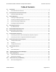
PVI 23TL & PVI 28TL Installation and Operation Manual PVI Series Inverters Table of Contents 1.0 1.1 2.0 2.1 3.0 Introduction ............................................................................................................................. 7 PVI 23‐28TL Inverter Enclosure ................................................................................................... 9 Site Preparation and Inverter Placement ................................................................................
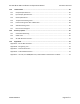
PVI 23TL & PVI 28TL Installation and Operation Manual 13.0 PVI Series Inverters Technical Data ...................................................................................................................... 46 13.1 Output AC Specifications .......................................................................................................... 46 13.2 Input DC (PV) Specifications...................................................................................................... 47 13.
PVI 23TL & PVI 28TL Installation and Operation Manual PVI Series Inverters 1.0 Introduction The PVI 23TL and 28TL are commercial, dual MPPT, three‐phase utility‐interactive, transformerless PV inverters designed to be interconnected to the electric utility grid. The inverter is listed for use with ungrounded PV arrays only. By following this manual, the inverter can be installed and operated safely.
PVI 23TL & PVI 28TL Installation and Operation Manual PVI Series Inverters Feeding power back to the grid involves the conversion of DC voltage from the PV array to grid compatible AC voltage by inverting DC to AC. This unit feeds power into a standard, three‐phase commercial, industrial, institutional, or electrical utility facility’s electrical system which is connected to the electrical grid.
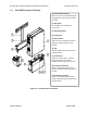
PVI 23TL & PVI 28TL Installation and Operation Manual 1.1 PVI Series Inverters PVI 23‐28TL Inverter Enclosure ① Inverter Main Housing Does not contain any serviceable parts; opening this section voids the inverter warranty. ② Wiring Box For customer’s AC and DC wire connections. ③ Moun ng Bracket 3 ④ Cooling Fans 4 1 4 2 ⑤ LED Indicators There are four LED indicators used to signal the operating status of the inverter. ⑥ LCD The LCD displays all measured values and parameters.
PVI 23TL & PVI 28TL Installation and Operation Manual PVI Series Inverters 2.0 Site Preparation and Inverter Placement The inverter is comprised of a NEMA 4 enclosure, containing electrical and electronic components as well as AC and DC integrated disconnects. NOTE: If the inverter is mounted outside, ensure that the wiring box remains closed during the installation process until access to the box is needed. This precaution will help to avoid damage due to rain, snow, or condensation.
PVI 23TL & PVI 28TL Installation and Operation Manual PVI Series Inverters The ambient temperature must be between ‐25°C and +45°C for full power and continuous operation. The inverter will automatically reduce power or may shut down to protect itself if ambient air temperature is outside the normal operating range.
PVI 23TL & PVI 28TL Installation and Operation Manual PVI Series Inverters 3.0 Inverter Mounting WARNING: Any lifting or moving of the inverter requires at least two people. Lifting of the crate/pallet requires at least three people. 3.1 Checking for Shipping Damage The inverter is thoroughly checked and tested rigorously before it is shipped.
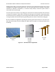
PVI 23TL & PVI 28TL Installation and Operation Manual 3.3 PVI Series Inverters Inverter Positioning and Mounting The Inverter can be mounted vertically or with a 15°–90° horizontal angle, as shown in Figure 3.1a below. Figure 3.1a – Allowable Inverter Mounting WARNING: Do not install the inverter tilted forward, lying on its back, or upside down as shown in Figure 3.1b. Figure 3.
PVI 23TL & PVI 28TL Installation and Operation Manual PVI Series Inverters 3.3.1 Wall Mounting The minimum distances that should be met for wall mounting are shown in Figure 3.2 below. For adequate cooling, there should be a minimum of ≥ 20 inches of space available between two adjacently mounted inverters. A minimum of 12 inches from the left side and 12 inches from the top are needed for adequate access and cooling.
PVI 23TL & PVI 28TL Installation and Operation Manual PVI Series Inverters 3.3.2 Wall Mounting/Mounting Bracket Clearance Figure 3.3 – Wall Mounting Clearance Requirements of Mounting Bracket 3.3.3 Pillar Mounting The minimum inverter mounting dimensions on a pillar are shown in Figure 3.4 below. 7.9in ¡ 2Ý00mm 23.6in ¡Ý 600mm 11.8in ¡ 3Ý00mm 11.8in ¡ 3Ý00mm 11.8in ¡ 3Ý00mm Figure 3.
PVI 23TL & PVI 28TL Installation and Operation Manual 3.4 PVI Series Inverters Installing the Mounting Bracket 9.84in. 9.8 (250mm) (2 4in. 50mm) NOTE: Always use all (8) mounting plate fasteners. 1 5.51in. (140mm) 20.55in. (522mm) 2 3 1. Mark the 8 holes on the load‐bearing surface using the available mounting bracket as a template (see Figure 3.5). 2. Drill 8 holes with a 13/32‐inch drill bit and install eight “M8 expansion tubes” (available in accessory box). 3.
PVI 23TL & PVI 28TL Installation and Operation Manual PVI Series Inverters 6. Using a #2 Philips screw driver, remove cover plate on the bottom of main housing. Figure 3.7 – Remove Cover Plate of Main Housing 7. Using a #2 Philips screw driver, remove cover of wiring box and keep the cover (it can be re‐secured later onto the enclosure). Figure 3.8 – Remove Cover of Wiring Box 8. Connect the wiring box to the main housing using four M6*16 screws (available in accessory box).
PVI 23TL & PVI 28TL Installation and Operation Manual PVI Series Inverters 9. Connect the main housing and wiring box to the mounting bracket using a #2 Philips screwdriver and six M5*10 bolts (available in accessory box). Torque = 14in‐lbs Figure 3.10 – Fasten the Main Housing and Wiring Box onto the Bracket 10. The previously removed cover box can be reattached to the left side of the wiring box (available in accessory box). Figure 3.11 – Attaching the Cover Board 11.
PVI 23TL & PVI 28TL Installation and Operation Manual PVI Series Inverters 4.0 Grounding Connections WARNING: All electrical installations must be performed in accordance with all applicable local electrical codes, and must be done by electrically qualified personal. Only make AC and DC grounding connections directly to the terminals within the wiring box. 4.1 DC and AC Grounds The inverter must be properly grounded in accordance with local code.
PVI 23TL & PVI 28TL Installation and Operation Manual PVI Series Inverters Figure 4.
PVI 23TL & PVI 28TL Installation and Operation Manual PVI Series Inverters 5.0 DC Connections from the PV Array WARNING: All wiring connections at the inverter must be performed with the building AC source circuit panel/breaker off and the PV module strings disconnected. AC and DC disconnect switches at the inverter must also remain off during termination. WARNING: All electrical wiring must be done by electrically qualified personal in accordance to local and national electrical code.
PVI 23TL & PVI 28TL Installation and Operation Manual 5.1 PVI Series Inverters Maximum Power Point Trackers The Inverter is designed with two separate MPP Trackers (Dual MPPT) which can operate independently or combined. The default option is two individual independent trackers. This option allows sites with shading and/or unbalanced string sizes to be connected to two separate zones, this allows for higher tracking efficiency and greater revenue.
PVI 23TL & PVI 28TL Installation and Operation Manual PVI Series Inverters WARNING: Strings must be balanced for optimum performance and revenue. When doing DC/AC ratio sizing, perform calculations on the zone level unless you intend to combine MPPT. Figure 5.3 – Typical DC Wiring Connection Figure 5.3 below shows the default status of the switch S401. Figure 5.
PVI 23TL & PVI 28TL Installation and Operation Manual PVI Series Inverters Figure 5.5 – Busbar Connection Used for Single (Combined) MPPT Option 5. Set switch S401 to parallel/combined (PAR) mode. Figure 5.6 – Switch Configuration for One Combined MPPT Zone Dual tracking MPPT might seem overwhelming at first, contact us at inverters@solectria.com If you have further questions, we are here to help. 5.3 DC Wiring 90°C PV copper conductors must be used for wiring for DC wiring.
PVI 23TL & PVI 28TL Installation and Operation Manual PVI Series Inverters Recommend PV Fuse Conductors Torque (ALL) Fuse Type DC inputs Configuration Max.
PVI 23TL & PVI 28TL Installation and Operation Manual DC Inputs/ MPPT Zones PVI Series Inverters S401 Switch Wire 2 Inputs ‐2 MPPT Zones IND 8 AWG 2 Inputs ‐ 1 MPPT Zone PAR 8 AWG Configuration Type Proper Wiring Table 5.
PVI 23TL & PVI 28TL Installation and Operation Manual PVI Series Inverters 6.0 AC Connections at the Inverter Both the PVI 23TL and PVI 28TL 3‐phase AC wiring is recommended to be installed with five conductors, one per phase along with a neutral and an AC equipment ground as per local requirements. WARNING: The terminal is rated for CU wire only. The integrated disconnect switch terminals are listed for 75°C wire. See NEC 310.
PVI 23TL & PVI 28TL Installation and Operation Manual 6.1 PVI Series Inverters AC Interconnections to Grid Description Configuration 4 Wire WYE (3 phase + Neutral +GND) Inverter Compatibility Compatible with 23TL Compatible with 28TL Other Configurations All other configurations not mentioned in this document, such as Corner Grounded Delta Not compatible with 23TL Not compatible with 28TL Table 6.
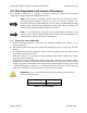
PVI 23TL & PVI 28TL Installation and Operation Manual PVI Series Inverters 7.0 Communication Connections PVI 23‐28TL inverters support industry standard RS‐485 Modbus communication. Below is information on the available communication interfaces. PAR IND ON S401 OFF S402 Communication board P203 P204 P207 P208 P205 3 4 Figure 7.
PVI 23TL & PVI 28TL Installation and Operation Manual Item # Port Name Item Name PVI Series Inverters Port Image Configuration Description 1 P205 Dry Contact Remote alarm option. Contact us at inverters@solectria.com for possible configuration. 2 P207 USB Port Port used for firmware upgrade. Not available for customer use. There are two RS‐485 signal ports on the inverter. 3 and 4 P203 and P204 RS‐485 RJ45 Port No. Color Function 1 White Orange 485+ 2 Orange N.C.
PVI 23TL & PVI 28TL Installation and Operation Manual 6 S402 120Ω Termination Switch for RS‐485 Communication 7 S401 MPPT Zone Configuration PVI Series Inverters 120 Ω resistor that can be added for impedance matching on the Modbus (RS‐485). This switch should only be turned on for the last inverter in the daisy chain. Used for changing between Dual and Single MPPT configuration. Covered in detail in Chapter 5. Table 7.1 – Available Communication Options in PVI 23‐28TL Inverter 7.
PVI 23TL & PVI 28TL Installation and Operation Manual 7.2 PVI Series Inverters Connecting TL Inverters using SolrenView Monitoring Option Solectria offers SolrenView monitoring option for the PVI 23‐28 TL inverters. This option includes the SolrenView data logger which can be integrated with the inverter’s wiring box. The SolrenView logger is used to connect the TL inverters to the Solectria SolrenView web based monitoring site.
PVI 23TL & PVI 28TL Installation and Operation Manual PVI Series Inverters 8.0 Commissioning the Inverter PV System Before commissioning, ensure that the inverter is mounted, all connections are made, and the inverter is ready to power up. NOTE: Make sure all tools, parts, etc., are removed from the vicinity of the inverter before turning it on. WARNING: Make a final check of all AC and DC wiring to the inverter and in the system before turning on.
PVI 23TL & PVI 28TL Installation and Operation Manual PVI Series Inverters 9.0 LCD and LED Indicators The inverter operates automatically without the need for user interaction. The LCD and LED indicators on the front of the inverter provide valuable operating information. 9.1 LCD POWER RUN GRID FAULT Figure 9.1 – LCD The four touch keys below are available to help the customer scroll through the information.
PVI 23TL & PVI 28TL Installation and Operation Manual PVI Series Inverters The LEDs on the left indicate the operational status of the inverter. LED Light Status Indication Light on DC voltage available at the inverter No need, Standard Operation Light off Low DC or possible power supply problem 1. Check DC input polarity is correct. 2. Verify DC voltage above 180VDC. 3. Verify DC disconnect switch is on.
PVI 23TL & PVI 28TL Installation and Operation Manual 9.2 PVI Series Inverters Screen Descriptions 9.2.1 Main Screen (Default) Press ESC to move from the Main (Default) screen into the Start Menu. 9.2.2 Start Menu 1. Operation Info 2. Alarm 3. History 4. Settings 5. Power Dispatch 9.2.3 Operation Info Menu The Info Menu displays the data stored in the inverter memory. Use the buttons to scroll UP will take the screen back to the Start Menu. and DOWN through the list.
PVI 23TL & PVI 28TL Installation and Operation Manual PVI Series Inverters 9.2.4 Alarm Menu The Alarm Menu displays inverter alarms and faults, some of which may be modified with the keypad. Use the and buttons to scroll up and down through the list. Pressing will take the screen back to the Start Menu. Any fault message will be indicated in the Alarm Menu. 2 Alarm No Yes NoError EepromErr Protect0010 … Figure 9.2 – Present Fault Information 9.2.
PVI 23TL & PVI 28TL Installation and Operation Manual PVI Series Inverters 9.2.6 Settings Menu The inverter parameters can be adjusted by using commands in the Settings Menu as shown in Figure 9.7 below. Options such as Power ON/OFF, Language, Sounds, Date, Communications, and MPPT can simply be changed/set from the Settings Menu. NOTE: When prompted for a password, enter the following: UP, DOWN, UP, DOWN, then ENT.
PVI 23TL & PVI 28TL Installation and Operation Manual PVI Series Inverters 9.2.7 Power Dispatch “ActivePower” and “PowerFactor” parameters can be set up through the LCD as well as remotely. NOTE: These parameters are only adjustable with permission from the local utility. Figure 9.5 – Active Power and Power Factor Settings NOTE: When prompted for a password, enter the following: UP, DOWN, UP, DOWN, then ENT. NOTE: It is often common at sites with High AC voltage above 1.05p.
PVI 23TL & PVI 28TL Installation and Operation Manual 10.0 PVI Series Inverters Troubleshooting and Inverter Messages Although the inverter is designed for many years of power production, there may be instances where error messages are displayed on the LCD. This table can be used to help identify the error and resolve it. Type Alarm Name Definition Abnormal 1. TempSensorErr temperature reading Possible Causes 1. Internal temperature sensor is making poor contact. 2. Temperature sensor is damaged.
PVI 23TL & PVI 28TL Installation and Operation Manual 2. Fan service life has ended. 3. Fan socket connecter is making a poor connection. Alarm Protection 5. EepromErr 1. Arc Board Error Incorrect memory reading Internal Arc board self‐check error 1. A problem with the inverter’s internal memory. 1. Possible communication error between Arc board and Inverter. 2. Abnormal reading within the Arc board. 1. Ambient temperature outside the inverter is too high. Protection 2.
PVI 23TL & PVI 28TL Installation and Operation Manual 1. Grid frequency is out of range. Protection 4. GridF.OutLim Grid voltage frequency is abnormal 2. Loose AC connections. Protection Protection Protection Protection PVI Series Inverters 1. Observe for 10min and see whether the alarm is cleared automatically. 2. Verify grid frequency is within range. 3. Verify proper AC wiring. 4. If error does not clear, Contact Solectria Customer Service.
PVI 23TL & PVI 28TL Installation and Operation Manual Protection Protection Fault 9. IntProtect 0010‐0260 10. Arc Protect 1. IntFault0010‐ 150 Internal problem within the inverter Inverter shuts down due to a possible Arc fault concern Internal non‐ critical fault within the inverter PVI Series Inverters 1. One of the inverter’s internal protection features was triggered causing the inverter to shut down. 1. Observe for 10min and see whether the alarm is cleared automatically. 2.
PVI 23TL & PVI 28TL Installation and Operation Manual PVI Series Inverters 11.0 Product Maintenance Regular maintenance helps extend product lifetime and performance. 11.1 Check the Electrical Connection Check all the cable connections once every 6 months, by performing the following steps: 1. Turn off inverter DC disconnect. 2. Turn off inverter AC disconnect. 3. Lock out all DC and AC sources to the inverter. 4. Verify absence of DC and AC voltages at the wiring box. 5.
PVI 23TL & PVI 28TL Installation and Operation Manual PVI Series Inverters 12.0 Product Warranty and RMA Policy 12.1 Warranty and Registration The warranty and RMA statements for this product are available online at http://www.solectria.com//site/assets/files/1091/inverter_warranty‐1.pdf. If you do not have access to the internet or would like to request a copy to be mailed to you, please contact the Solectria Renewables Customer Service Department at 978‐683‐9700.
PVI 23TL & PVI 28TL Installation and Operation Manual PVI Series Inverters 13.0 Technical Data 13.1 Output AC Specifications The inverters are designed to feed power into a standard 60Hz, three‐phase AC utility service provided within a facility with a rating of not less than the rating of the inverter(s) connected to it. The inverter is designed to work with the range of AC voltages for a three‐phase service defined by IEEE 1547‐2003 and ANSI C84.1.
PVI 23TL & PVI 28TL Installation and Operation Manual PVI Series Inverters 13.2 Input DC (PV) Specifications PVI23TL Absolute Maximum Input Voltage Maximum PV Power Operating Input Voltage Strike (Startup Voltage/Power) MPPT Input Voltage Range MPPT Trackers Maximum Operating Input Current Maximum Short Circuit Current PVI 28TL Units VDC 1000 15.
PVI 23TL & PVI 28TL Installation and Operation Manual PVI Series Inverters 13.4 Temperature Derating Curve Figure 13.1 shows the standard power derating curve for a PVI 23‐28TL inverter. The inverter operates at full power up to 45°C and derates linearly until 60°C where it shuts down to protect itself. Figure 13.1 – Temperature Derating Curve 13.5 Power Derating Curve Out of MPPT Zone Figure 13.2 below shows the standard derating curve outside of the MPPT zone.
PVI 23TL & PVI 28TL Installation and Operation Manual PVI Series Inverters 13.6 Altitude Derating Curve Po/Pn Figure 13.3 – Derating at High Altitudes 13.7 Internal Circuit Diagram The basic power flow within the PVI 23‐28TL series of inverters is below. Note that the GFDI circuit is not depicted. PV FUSE DC Switch MPPT1 PV1+ PV1+ PV1+ PV1+ AC Output Three level inverter N PV1+ PV1‐ PV1‐ PV1‐ PV1‐ PV1‐ L1 L2 MPPT2 PV2+ PV2+ PV2+ PV2+ L3 PV2+ PV2‐ PV2‐ PV2‐ PV2‐ PV2‐ PE AFD Figure 13.
PVI 23TL & PVI 28TL Installation and Operation Manual PVI Series Inverters 14.0 Accessory Options The PVI 23‐28TL comes with several options that allow the inverter to support a wide range of real life applications. 14.1 SolrenView Monitoring OPT‐SRV‐LCD, as discussed in Section 7.2, allows customers to purchase the only monitoring system that is designed to support PVI 23‐28TL to the fullest. SolrenView can be placed inside the inverter so no external enclosure is needed.
PVI 23TL & PVI 28TL Installation and Operation Manual PVI Series Inverters Figure 14.2 below shows an inverter installed rack mounted with the Solectria Shade cover. Figure 14.2 – Inverter With Shade Cover Installed 14.3 AC & DC Disconnect Covers OPT‐DISCOCOVER‐PVI‐23‐28 is a tamper resistant cover for the AC and DC disconnects. It is for customers that have inverters in public places so the disconnects cannot be turned while the inverter is running. Figure 14.
PVI 23TL & PVI 28TL Installation and Operation Manual PVI Series Inverters 15.0 Appendices Appendix A – PVI 23‐28TL Datasheet http://www.solectria.com/support/documentation/ Appendix B – String Sizing Tool http://solectria.com/support/string‐sizing‐tool/ Appendix C – Contact Information Solectria Renewables, LLC 360 Merrimack Street Lawrence, Massachusetts 01843 USA Tel: Fax: Sales Support: Customer Support: Website: 978.683.9700 978.683.9702 inverters@solectria.com service@solrectria.com www.
PVI 23TL & PVI 28TL Installation and Operation Manual PVI Series Inverters Appendix E – UL 1741 / UL 1699B/ IEEE 1547 / CSA 22.2#107.