PVI 36TL INSTALLATION AND OPERATION MANUAL Revision B ©2015, Yaskawa- Solectria Solar
PVI 36TL Installation and Operation Manual PVI Series Inverters IMPORTANT REGISTRATION AND WARRANTY INFORMATION For warranty to become active, this inverter must be registered. To activate warranty and register inverter, please visit the link below. www.solectria.
PVI 36TL Installation and Operation Manual PVI Series Inverters Before You Start… This manual contains important information regarding installation and safe operation of the PVI 36TL. Be sure to read this manual carefully before using the inverter. Thank you for choosing a Solectria grid-tied PV Inverter. This PV Inverter is high performance and highly reliable product specifically designed for the North American Solar market.
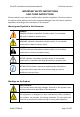
PVI 36TL Installation and Operation Manual PVI Series Inverters IMPORTANT SAFETY INSTRUCTIONS SAVE THESE INSTRUCTIONS Please read this user manual carefully before product installation. Solectria reserves the right to refuse warranty claims for equipment damage if the user fails to install the equipment according to the instructions in this manual. Warnings and Symbols in this Document DANGER: DANGER indicates a hazardous situation which, if not avoided, will result in death or serious injury.
PVI 36TL Installation and Operation Manual PVI Series Inverters EARTH GROUND: This symbol marks the location of grounding terminal, which must be securely connected to the earth through the PE (Protective Earth) cable to ensure operational safety. WARNING: All of the installation and wiring connections should be performed by qualified technical personnel. Disconnect the inverter from PV modules and the AC Grid before maintaining and operating the equipment.
PVI 36TL Installation and Operation Manual PVI Series Inverters Table of Contents 1.0 Overview................................................................................. 7 1.1 Inverter for Grid-Tied PV Systems ............................................. 7 1.2 Product Features ....................................................................... 7 1.3 Product Protection Functions .................................................... 8 1.4 Circuit Structure Design ..................................
PVI 36TL Installation and Operation Manual PVI Series Inverters 6.1 Fault Shutdown and Troubleshooting ..................................... 82 6.2 Product Maintenance .............................................................. 87 6.3 Uninstalling the Inverter .......................................................... 92 7.0: Technical Data ...................................................................... 93 8.0: Accessory Options ................................................................
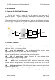
PVI 36TL Installation and Operation Manual PVI Series Inverters 1.0: Overview 1.1 Inverter for Grid-Tied PV Systems The PVI 36TL inverter is suitable for use for commercial and large scale PV grid-tied systems. A system is generally made up of PV modules, DC power distribution equipment, PV inverter and AC power distribution equipment (Figure 1.1). The inverter converts DC from PV modules to AC with the same frequency and phase as the AC grid.
PVI 36TL Installation and Operation Manual PVI Series Inverters 1.
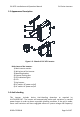
PVI 36TL Installation and Operation Manual PVI Series Inverters 1.5 Appearance Description 3 1 4 4 2 9 8 5 6 7 Figure 1.3 - Sketch of PVI 36TL Inverter Main Items of the Inverter: 1) Main inverter section 2) Wiring box of the inverter 3) Mounting bracket 4) External cooling fans 5) LED indication lights 6) LCD 7) Key buttons 8) DC switch: DC power on/off 9) AC switch: AC power on/off 1.6 Anti Islanding This inverter includes Active Anti-Islanding detection as required by UL1741/IEEE1547.
PVI 36TL Installation and Operation Manual PVI Series Inverters However, in an islanded condition the small amount of reactive power changes will force the system voltage or frequency to change significantly, which will trigger the inverter to shut down. 1.7 DC Ground Fault Protection The PVI 36TL includes residual current detection as part of the DC ground fault detection method as required by UL1741.
PVI 36TL Installation and Operation Manual PVI Series Inverters (2) Wiring box 1 (3) Mounting bracket 1 Upon which inverter is hung and mounted onto a wall (4) User manual 1 Installation and operation manual (5) Accessory kit 1 Contains all necessary accessories The (5) Accessory kit contains items listed below: Table 2.2 - Accessories No.
PVI 36TL Installation and Operation Manual PVI Series Inverters (11) RJ45 connecter 4 For RS-485 or Ethernet communication, 2 spare parts (12) 5 pin connector 1 For RS-485 communication (13) 3 pin connector 1 For dry contact communication (14) Jumper busbar 2 For parallel mode use INSTRUCTION: The items in the accessory kit table above are for the standard configuration. The accessories may vary if optional parts are purchased. 2.
PVI 36TL Installation and Operation Manual PVI Series Inverters 2.2 Mechanical Installation 1) Dimensions Figure 2.
PVI 36TL Installation and Operation Manual PVI Series Inverters 2) Installation Method (see Figure 2.2): Make sure that the mounting structure (wall, rack, etc.) is suitable to support the inverter weight. Follow the mounting guidelines below: (a) If the location permits, install the inverter vertically. (b) If the inverter cannot be mounted vertically, it may be tilted backward but no lower than 15 degrees from horizontal. (c) Do NOT mount the inverter leaning forward.
PVI 36TL Installation and Operation Manual PVI Series Inverters NOTICE: When the inverter is mounted at an angle ≤15° outdoor, shade cover is recommended to be installed above the inverter to avoid direct sunlight. 3) Installation Space Requirement (see Figure 2.3): The distances between the inverters or the surrounding objects should meet the following conditions: NOTICE: The spacing between two adjacently mounted inverters should be ≥500mm (19.7 inches).
PVI 36TL Installation and Operation Manual 7.9in ¡Ý 200mm PVI Series Inverters 23.6in ¡Ý 600mm 11.8in ¡Ý 300mm 11.8in ¡Ý 300mm 11.8in ¡Ý 300mm Figure 2.4 - Inverter Pillar Mounting Specifications INSTRUCTION: If the inverter is installed on Unistrut or the array racking (instead of solid wall), the space from the bottom of one inverter to the top of the inverter below may be as small as 4in (100mm).
PVI 36TL Installation and Operation Manual PVI Series Inverters 813mm(min.) (32in.) 522mm (20.55in.) 140mm(5.51in.) 550mm(min.) 250mm 250mm (21.7in.) (9.84in.)(9.84in.) 425mm(min) (16.7in.) 4) Mounting the Inverter Onto the Bracket (1) Mark the 8 holes on the bearing surface for mounting the bracket as shown in Figure 2.5; 1100mm(min.) (43.3in.) Figure 2.5 - Holes on the Bearing Surface Dimensions (2) Drill holes at the marked positions with a 10mm (0.4in.
PVI 36TL Installation and Operation Manual 2 2 3 3 20.55in. (522mm) 1 5.51in. (140mm) 1 PVI Inverters 9.84inSeries . 9. (250mm) (2 84in. 50mm) Figure 2.6 - Securing the Mounting Bracket (3) Hang the inverter onto the mounting bracket as shown in Figure 2.7 and Figure 2.8; Lift mounting: Take out the lifting eye nut M10 (2pcs) from the accessory kit, and screw them onto the studs at the top of the inverter.
PVI 36TL Installation and Operation Manual PVI Series Inverters Figure 2.8 - Grab Handle Position (4) Installing the wiring box ① Remove the cover plate at the bottom of the main section. (see Figure 2.9) Tool: No.2 Phillips head screwdriver Figure 2.9 – Main Section Cover Plate ② Remove the cover at the top of the wiring box (see Figure 2.
PVI 36TL Installation and Operation Manual PVI Series Inverters Figure 2.10 - Wiring Box Cover ③Connect the wiring box to the main section, using M6x16 screws (4pcs) to secure the wiring box. (see Figure 2.11) Tool: No. 10 Wrench, torque value of 25 in-lbs (2.8N.m ) Figure 2.11 - Wiring Box Installation CAUTION: The total weight of the PVI 36TL main inverter section and wiring box is 66kg (146 pounds).
PVI 36TL Installation and Operation Manual PVI Series Inverters (5) Attach the main section and the wiring box to the mounting bracket with the M5x10 bolts (6 pcs). (see Figure 2.12) Tool: No.2 Phillips head screwdriver, torque value of 1.6N.m (14 in-lbs) Figure 2.12 - Secure the Main Section and Wiring Box to the Bracket (6) Optional - Install an anti-theft padlock when the installation is complete.
PVI 36TL Installation and Operation Manual PVI Series Inverters Figure 2.13 - Anti-Theft Padlock Location The anti-theft padlock should meet the requirement of the dimensions shown in Figure 2.14: B A C Recommended lock size: A: Ф3~6mm B: 20~50mm C: 20~50mm Figure 2.14 - Dimensions of Anti-Theft Padlock 5) Removing/Replacing the Wire Box Cover: (1) Use a #3 Phillips screwdriver to remove the 4 screws on the wiring box and pull cover straight off the box.
PVI 36TL Installation and Operation Manual PVI Series Inverters Figure 2.15 – Removing the Wiring Box Cover (2)To replace the cover use a #3 Phillips screwdriver to replace the 4 screws on the cover. INSTRUCTION: It is important to use a hand tool (e.g. Screwdriver or T-handle, #3 Phillips) and not power drivers or other types of screw drivers. Also, it is important to hold the cover in alignment with balanced force across the cover, not weighted toward any edge.
PVI 36TL Installation and Operation Manual PVI Series Inverters 2.3 Electrical Installation The connection interface of PVI 36TL inverter: Figure 2.
PVI 36TL Installation and Operation Manual PVI Series Inverters 20.7in(525mm) 19.1in(485mm) 18.7in(475mm) 14.8in(377mm) 5.4in (137mm) 10.1in (257mm) 7 DC INPUT AC OUTPUT COMM. PORT WARNING: High touch current . Earth connection essential before connecting supply. � For more details please see the user manual. 5 1 2 3 4 6 Figure 2.17 - External Connection Ports 8 9 8 8 8 9 10 Figure 2.18 - Internal Connection Points 1. Knockout for DC input cable, 1-1/4inch 2.
PVI 36TL Installation and Operation Manual PVI Series Inverters Choose the cables for inverters according to the following configuration table: Position DC input (﹢/﹣) AC output (L1/L2/L3/N) PE RS-485 communication Table 2.3 - Cable Specifications Cable DC cables specifications refer to Table3-6 #6~1AWG(Copper) #4~1AWG(Aluminum) #10~6AWG(Copper) #6AWG recommended(Copper) #4AWG recommended (Aluminum) #8AWG recommended (Copper) UTP CAT-5e or 3x#22~18AWG communication cable (eg.
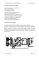
PVI 36TL Installation and Operation Manual PVI Series Inverters 2.3.1 DC Connection 1) Working Mode PVI 36TL inverter has two PV input sections: DC Input-1 and DC Input-2. These two sections can work in “Parallel mode” or “Independent mode” (see Figure 2.20). The default setting from the factory is “Independent mode”. In Parallel mode, the two PV input sections share one MPP Tracker; In Independent mode, each PV input section works with independent MPP Tracker.
PVI 36TL Installation and Operation Manual Inverter model PVI 36TL PVI Series Inverters Table 2.4 - DC Input Power Specification Max. DC input power Rated DC input power of (Parallel mode) each input section (Independent modeDefault from factory) 37kW (70A) 18.5kW (35A) Note: The standard configuration is “Independent mode”. If it needs to switch to the “Parallel mode”, please take the following steps to change the internal configuration: 1. Remove the cover of the wiring box. (see Figure 2-15) 2.
PVI 36TL Installation and Operation Manual PVI Series Inverters Jumper busbar Figure 2.21(b) Figure 2.
PVI 36TL Installation and Operation Manual PVI Series Inverters Selector switch for PV connection mode 1-----independent mode 2-----parallel mode Figure 2.22 – PV Connection Mode Selector Switch Location 2) DC Fuse Configuration PVI 36TL inverters are equipped with standard 15A DC fuses. Customers must verify that the appropriate fuses are installed depending on the actual configuration of PV strings. (a) Each independent string of DC input from the PV strings needs fuse protection.
PVI 36TL Installation and Operation Manual PVI Series Inverters 3) DC Cable Connection To ensure the optimum performance of the inverter, please read the following guidelines before DC connection: (a) Confirm the DC configuration referring to Table 2.5 and ensure that the maximum open circuit voltage of the PV modules is lower than 1000 VDC under any conditions. (b) Confirm that the PV strings for each MPPT of the inverter are of the same type and specification before connection.
PVI 36TL Installation and Operation Manual PVI Series Inverters *Consider combining MPPT zones for such configurations **Use Inline fuses to adhere to module series fuse rating if necessary Note: When using Y connectors to combine two strings you have to use a UL listed parts such as: Amphenol Overmolded Solar Junction. When combining 2 strings you should use a Y connector that has a fuse in each branch equal to the module series fuse rating. For 9 inputs you can place the 30A fuse in any fuse holder.
PVI 36TL Installation and Operation Manual PVI Series Inverters Figure 2.24 - DC Input Cables Set Up (g) Connect the crimped DC cables to the terminal block on the circuit board and fasten the screws, as shown in Figure 2.25: Tools: 6mm (0.23in.) flat screwdriver Torque value: 3.4N-m (30 in-lbs) Figure 2.25(a) - DC Input Cable Specifications Figure 2.
PVI 36TL Installation and Operation Manual PVI Series Inverters 1 2 PV1+ 3 IN1+ 4 1 PV2 + 2 Inv 2+ 3 4 1 2 PV1- 3 Inv 1- Inverter 4 1 PV2- 2 3 IN2- 4 Figure 2.26 - Two MPPTs Operating Independently Independent mode can be very helpful for sites with shading on parts of the array. However, this also means that one must consider these two zones as two separate inverters and power must be balanced as much as possible between the two MPPT zones.
PVI 36TL Installation and Operation Manual PVI Series Inverters Figure 2.27 - Two MPPTs Combined to Operate as One When the copper jumpers are installed across DC+ and DC- this allows the power to be evenly distributed between the two trackers such as applications of odd number of strings. Note 1: The temperature rating of the input wirings should be no less than 90°C (194°F). Note 2: The recommended fuse types are configured according to the condition that the input strings are the same. 2.3.
PVI 36TL Installation and Operation Manual PVI Series Inverters Figure 2.28 - Remove the Wiring Box Cover No. 1. 2. 3. 4. 5. 6. 7. Table 2.7 - Required Tools Tools #3 Phillips screwdriver 1/4” flat head bit 1/8” flat head bit Torque driver Diagonal pliers Wire stripping pliers Crimping pliers Table 2.8 - Torque Values AC output terminal block Internal grounding bar Internal grounding stud External grounding point DOCR-070588-B 30 in-lbs (3.5 N-m ) 14 in-lbs (1.6 N-m ) 14 in-lbs (1.
PVI 36TL Installation and Operation Manual PVI Series Inverters COMM. PORT WARNING: High touch current . Earth connection esse before connecting sup � For more details please see the user manual. Figure 2.
PVI 36TL Installation and Operation Manual PVI Series Inverters COMM. PORT WARNING: High touch current . Earth connection esse before connecting sup � For more details please see the user manual. Figure 2.29(b) - AC Output and Ground Cable Connections Pre-insulated end ferrule 4pcs Core wire Pre-insulated end ferrule Figure 2.
PVI 36TL Installation and Operation Manual PVI Series Inverters Pre-insulated end ferrule 3pcs OT type terminal,1pcs Core wire Pre-insulated end ferrule Core wire OT type terminal Figure 2.31 - AC Output and Ground Cable Set Up (2) Connect the AC (L1, L2, L3) cables to the terminal block and use the OT type terminal to connect the ground cable to the external grounding point at the bottom of rd the wiring box. (see the 3 graph in Figure 3-27 ) Set up the cables referring to Figure 2.30.
PVI 36TL Installation and Operation Manual PVI Series Inverters 4) When the output of the inverter is connected to the grid, an external AC circuit breaker is required to be installed to safely disconnect the inverter from the grid when overcurrent occurs. 5) The Grid connection type could be optional, which can be (L1,L2, L3,N,PE) or(L1,L2, L3,PE) . Either 3 pole or 4 pole AC circuit breaker should be selected as per the following specifications: Table 2.
PVI 36TL Installation and Operation Manual PVI Series Inverters 2.4 Inverter Communication Connections The PVI 36TL inverters support industry standard Modbus RS-485 communications. PAR IND S401 ON OFF S403 S402 Figure 2.
PVI 36TL Installation and Operation Manual Item Picture 1 2 PVI Series Inverters Configuration description P205 - Dry Contact Communication Port (3 Pin Connector) Please see section 2.4.3 Dry contact communication for more details. N.O. N.C.
PVI 36TL Installation and Operation Manual PVI Series Inverters 2.4.1 Modbus (RS-485) Network Connections with External Monitoring Systems The PVI 36TL inverter can be connected to an external Data Acquisition System (DAS) via Modbus (RS-485) connection as shown in figure 2.33. Figure 2.
PVI 36TL Installation and Operation Manual PVI Series Inverters 3-35. S402 should always be left in the off position except for the last inverter in the daisy chain. • Star or T Modbus (RS-485) network topologies should always be avoided. See Figure 2.34. Figure 2.34 It is important to daisy chain the inverter Modbus (RS-485) connections to minimize noise and bus reflections. Any network topologies shown to the left should be avoided.
PVI 36TL Installation and Operation Manual PVI Series Inverters Connecting External DAS Modbus (RS-485) Network to the PVI 36TLInverter: Warning: Risk of Electric Shock. Make sure all DC and AC power to the unit has been disconnected before opening the inverter wiring box and make sure hazardous high voltage and energy inside the equipment has been discharged. 1. Open the inverter wiring box. 2. Bring the cable into wiring box through knockout holes at the bottom. 3.
PVI 36TL Installation and Operation Manual PVI Series Inverters Figure 2.36 The above image shows the Modbus (RS-485) cable connection where the Modbus daisy chain ends. Notice how the cable shield is not landed inside the inverter. The Modbus termination switch (S402) is in the on position. 5. IMPORTANT: The cable shield should only be connected to ground (GND) at the external DAS.
PVI 36TL Installation and Operation Manual PVI Series Inverters Figure 2.37 Notice how the cable shield is daisy chained together and not landed inside the inverter. S402 is in the OFF position, or down towards the Phoenix connector when the inverter is in the middle of the daisy chain. Warning: Risk of Electric Shock. Make sure all shield wires are properly secured and insulated to prevent shorting to any other components inside the inverter. 6. 7. 8. Close the wiring box.
PVI 36TL Installation and Operation Manual PVI Series Inverters 2.4.2 Modbus (RS-485) Network Connections with SolrenView Data Logger If the PVI 36TL inverters are ordered with SolrenView data monitoring services from the factory, the SolrenView data logger is installed in the factory in one of the inverters. This inverter should be installed as Inverter number 1 in the Modbus daisy chain as shown in Figure 2.38. Figure 2.
PVI 36TL Installation and Operation Manual PVI Series Inverters Connecting the Ethernet Router/Firewall to the SolrenView Data Logger: The SolrenView Data logger is connected to the customer provided Ethernet router/firewall utilizing a Cat 5e or better Ethernet cable as shown in figure 2.38. The Ethernet cable length must be kept shorter than 328ft (100m) to ensure trouble free communications. Figure 2.39. - SolrenView Data Logger Connections.
PVI 36TL Installation and Operation Manual PVI Series Inverters Connecting the Modbus (RS-485) Network to the PVI 36TL Inverters with SolrenView Data Logger: Warning: Risk of Electric Shock. Make sure all DC and AC power to the unit has been disconnected before opening the inverter wiring box and make sure hazardous high voltage and energy inside the equipment has been discharged.
PVI 36TL Installation and Operation Manual PVI Series Inverters Figure 2.40 - The SolrenView Data Logger Printed Circuit Board and the Modbus Termination Dip Switches. 5. 6. Extend the Modbus cable shield with additional wire so that it can reach to the Chassis GND terminal block as shown in Figure 2.41. The wire should be soldered to the cable shield to ensure solid and reliable connection.
PVI 36TL Installation and Operation Manual PVI Series Inverters Figure 2.41 - SolrenView Data Logger Installed Inside the PVI 36TL Wiring Box. Notice how the Modbus cable shield is grounded by extending the Modbus cable shield with a wire and connecting it to the inverter chassis GND terminal. The external Modbus cable is connected to P208 sharing the +/- RS-485 connections with the SolrenView data logger.
PVI 36TL Installation and Operation Manual PVI Series Inverters 7. Follow steps 5 through 8 in section 2.4.1 Modbus (RS-485) Network Connections with External Monitoring Systems to connect other inverters in the daisy chain. Warning: Risk of Electric Shock. Make sure all shield wires are properly secured and insulated to prevent shorting to any other components inside the inverter.
PVI 36TL Installation and Operation Manual PVI Series Inverters 2.4.3. Dry Contact Communication The inverter features an alarm function that opens or closes a dry contact on the communication board. (available both as contact normally open – N.O. – and as contact normally closed – N.C.), as shown below: N.O. N.C. COM Figure 2.34 - Dry Contact Communication Port The voltage and current rating of the dry contact shown in the following table must not be exceeded under any circumstances. Table 2.
PVI 36TL Installation and Operation Manual PVI Series Inverters Connection Plan: You can connect a LED or other loads to indicate the operational status of the inverter, as shown in the following figure: (or L + Line circuit Breaker( 3 A) COM (or L N) + - - Line circuit Breaker( 3 A) COM N.C. N.C. N.O. N.O. COM COM N.C. N.C. N.O. N.O. COM COM N.C. N.C. N.O. N.O. Light on in trouble free operational N) Fault In operation In operation Light on in error Figure 2.
PVI 36TL Installation and Operation Manual PVI Series Inverters Tool: Wire stripping pliers A D L2 L1 Figure 2.36 - Wire Stripping Table 2.13 Cable Set-Up Description Position Cable type Value Double-layer insulated cable D Outer diameter 4.5 mm~ 6 mm A Cross-section area of conductor 0.2 mm² ~ 0.75 mm² L1 Length of stripped outer wire skin Maximum 15mm L2 Length of stripped inner wire skin Maximum 7 mm d.) Connect wires to the terminal. Tool: 2 or 2.5mm flat screwdriver No.
PVI 36TL Installation and Operation Manual PVI Series Inverters e.) Plug the cable terminal into the P205 connector. Figure 2.
PVI 36TL Installation and Operation Manual PVI Series Inverters 3.0: Commissioning WARNING: Please follow the guidelines below before on-grid operation to eliminat possible dangers and to ensure safety. 3.1 Commissioning Checklist 3.1.1 Mechanical Installation Make sure that the mounting bracket is secure and all the screws have been tightened to the specified torque values. (Please refer to 2.2 Mechanical Installation) 3.1.
PVI 36TL Installation and Operation Manual PVI Series Inverters (d) When the inverter completes “sys checking”, the LCD shows the screen as Figure 3.1 below. Press ENTER to the standard selection interface, as shown in Figure 3.2. (e) Select the corresponding grid standard and press ENTER. Set Standard! Figure 3.1 - Set Up Grid Standard →1 2 3 4 Rule 21 IEEE 1547 HECO-ML HECO-OHM Figure 3.2 - Select Grid Standard 5.) When the LCD shows the normal operation status (Figure 3.
PVI 36TL Installation and Operation Manual PVI Series Inverters 4.0: User Interface 4.1 Description of LCD The inverter’s LCD mainly consists of LCD, LED indicator lights, buzzer and 4 keys, as shown in Figure 4.1. POWER RUN GRID FAULT Figure 4.1 - LCD Interpretation for the indicator lights is shown in Table 5-1 and function of the keys is shown in Table 4.2. Table 4.
PVI 36TL Installation and Operation Manual light FAULT Fault status indication light Light off Light on Slow flash Fast flash Light off PVI Series Inverters Power supply not working Indicates a Fault Indicates Alarm (light on 0.5s, light off 2s) Protective action (light on 0.5s, light off 0.5s) No fault or power supply not working Table 4.
PVI 36TL Installation and Operation Manual PVI Series Inverters according to the indications of the LCD. (1) The LCD interface starts with the company logo once the system is energized, as shown in Figure 4.2. Figure 4.2 - Logo Screen (2) Indication of inverter operation mode: Sys.Checking >>>>>> Figure 4.3 - Inverter System Check Ongoing Standby >>>>>> Figure 4.4 - Inverter System in Standby Mode PV1 730 V 14.0A 08/12 13:10:05 (a) 277 20.2 223.2 PV2 729 V 14.2A 277 20.5 223.
PVI 36TL Installation and Operation Manual PVI Series Inverters GridV.OutLim Figure 4.6 - Fault Indication Interface LCD will display different mode interfaces based on the operation modes of the inverter. There are four operation modes: startup system check mode (as shown in Figure 4.3), stand-by mode (as shown in Figure 4.4), normal operation mode (as shown in Figure 4.5, the switching time between (a) and (b) is 5 seconds), and fault mode (as shown in Figure 4.6).
PVI 36TL Installation and Operation Manual 1 OP.Info PVI Series Inverters EDay 23.5kWh PDayPk 19kW DayT 12 .1 h Uab Ubc Uca Freq 480.2V 480.5V 479.7V 60.0Hz Ia Ib Ic 20.1A 19.8A 20.0A Tmod Tamb 78.2C 50.1C Upv 1 Ipv1 Upv 2 Ipv2 452.0V 18.9A 453.4V 18.7A Sac Pac 16.8KVA 16.5kW Figure 4.8 - Operation information indication (PV independent mode) Remarks:The LCD is shown with PV parallel mode selected. Upv Ipv 453.0V 18.7A Figure 4.
PVI 36TL Installation and Operation Manual PVI Series Inverters 4.4.2 Alarm As previously noted, if a fault occurs during normal operation of the inverter, corresponding fault messages will be indicated in “2 Alarm” menu in addition to the sound and light alarms. Move the cursor to “2 Alarm” and press ENT to check out the specific fault information, as shown in Figure 4.10. 2 Alarm No No Alarm Yes EepromErr Protect0010 … Figure 4.
PVI 36TL Installation and Operation Manual PVI Series Inverters 4.4.3 History Move the cursor to “3 History” in the main interface. Press ENT to check the history information, as shown in Figure 4.11. There are 4 submenus in “3 History”: “1 HistErr”, “2 OP. Recd”, “3 Version” and “4 TotalTag”. (1) The error log can store up 100 fault messages in “1 HistErr” menu. (2) The last 21 days of operation history data is available to be checked in “2 OP. Recd” menu.
PVI 36TL Installation and Operation Manual PVI Series Inverters 4.4.4 System Configuration Move the cursor to “4 Setting” in the main interface. Press ENT to enter the password: UP -> DOWN -> UP -> DOWN. Press ENT to confirm, and set the current system parameters, as shown in Figure 5-12. There are 7 submenus in “4 Setting”: “1 ON/OFF”, “2 Language”, “3 Buzzer”, “4 SysTime”, “5 Commun.”, “6 OtherCmd” and “7 NetConfig”.
PVI 36TL Installation and Operation Manual PVI Series Inverters The inverter will stand by instead of working normally if the startup conditions do not meet the needed values even if “ON” is selected. The inverter will shut down immediately if “OFF” is selected in any case. (2) Five languages, i.e. English, French, Chinese, German, and Italian are available in “2 Language” menu. (3) Key beep and Alarm beep can be set mute/unmute in “3 Buzzer” menu.
PVI 36TL Installation and Operation Manual PVI Series Inverters interface if the MPPT scanning succeeds, or remain on the “MPPTScan menu” interface if the scanning fails. (7) Configure the network address in the “7 NetConfig” menu. Move the cursor to the menu, press ENT and set up the parameters by UP and DOWN. Note if you have a daisy chain you cannot have two devices (inverters or other Modbus devices) with the same network ID.
PVI 36TL Installation and Operation Manual PVI Series Inverters 1 GridVProtect 2 GridFProtect 3 ON/OFF 4 PowerContr 5 LVRTSet 6 OtherProtect →1 SysPara. 2 Restart 3 Recover 4 ClrErrRecd Pls Input Pwd **** Are You Sure? 5 StdSet Pwd Error Pls Input Again **** Wrong Pwd Initialization? Restarting.. Recovering..
PVI 36TL Installation and Operation Manual PVI Series Inverters to “5.2 Shut down” after the inverter stops working, and choose the grid standard as per the local requirement of the electricity supply company. NOTICE: Please don’t change the grid standard when the inverter is in normal operation mode, or the change is invalid. Please refer to the “5.2 Manual Shutdown” to turn off the inverter. INSTRUCTION: PVI 36TL PV inverter supports 4 grid standards.
PVI 36TL Installation and Operation Manual GridVmaxRecT(V) GridVminRecT(V) GridVRecT(S) GridF.Max1(Hz) FmaxTripT1(S) GridF.Min1(Hz) FminTripT1(S) GridF.Max2(Hz) FmaxTripT2(S) GridF.Min2(Hz) FminTripT2(S) GridFmaxRecT(Hz) GridFminRecT(Hz) GridFRecT(S) GridV.Unbal(%) Recovery threshold value of Max. grid voltage Recovery threshold value of Min. grid voltage Recovery time of grid voltage protection Protection threshold value of Level 1 Max. grid frequency Trip time of Level 1 Max.
PVI 36TL Installation and Operation Manual PVI Series Inverters SoftOffOption Soft turn off option {Disable, Disable, Enable} OffPStep(KW/S) Turn off power step {0.01, 2.16,2.88} IsoResis(KOhm) Isolation resistance {10.0, 250.0 1000.0} GridReStep(KW/S) Grid fault recovery step {0.01, 0.05, 2.88} (3) ”4 PowerContr” menu: relative functions of active, reactive power control and over-frequency derating, including “ActiveContr(%)”, “RePowerContr” and ”FreqDeratCtrl” menus. 1.
PVI 36TL Installation and Operation Manual PVI Series Inverters Note: The power factor changes according to the power change, as shown in Figure 4.16: INSTRUCTION: The PF (P) Curve function is only available for VDE-4105, CEI 0-21 and IEEE-1547 grid standards. PF (PFCurveP1,PFCurvePF1) Inductive 1 (P%) -1 Capacitive (PFCurveP2,PFCurvePF2) Figure 4.16 - PF(P) Curve Mode 6). Q(U) Curve:Q(U) curve mode Note: The reactive compensation changes according to the grid voltage change, as shown in Figure 4.17.
PVI 36TL Installation and Operation Manual PVI Series Inverters Q(%) (QuCurveU2i,QuCurveQ2i) Inductive + _ (QuCurveU1, QuCurveQ1) (QuCurveU1i, QuCurveQ1i) U(V) Capacitive (QuCurveU2,QuCurveQ2) Figure 4.17 - Q(U) Curve Mode The Table 5-5 lists the parameters of QReactSet, PF Set, PF(P) Curve and Q(U) Curve modes. Press ENT to start up the modes after the parameters are set up. Mode Table 4.
PVI 36TL Installation and Operation Manual PVI Series Inverters QuCurveQ2(%) (-100.0%, -50.0%, 100.0%) See Figure 5-18 QuCurveU1i(V) (422.4, 441.6, 480.0) See Figure 5-18 QuCurveQ1i(%) (-100.0%, 0.0%, 100.0%) See Figure 5-18 QuCurveU2i(V) (422.4, 432.0, 480.0) See Figure 5-18 QuCurveQ2i(%) (-100.0%, 50.0%, 100.0%) See Figure 5-18 QuCurvTripP(%) (5.0%, 20.0%, 100.0%) Qu curve trip power QuCurveReP(%) (5.0%, 5.0%, 100.0%) Qu curve revocation power 3.
PVI 36TL Installation and Operation Manual PVI Series Inverters ARC Protect Figure 4.18 - ARC Protect Fault In the “System Setting””OtherCmd” menu, execute the “AFCI Test”, the inverter will stop working and test AFCI. When the test is over, “TestFinish” will be displayed on the LCD if no fault is detected or “AFCI Fault” will be shown if a fault occurs, as shown in Figure 4.20. MPPT Scan AFCI Test Testing Figure 4.19 - AFCI Test MPPT Scan AFCI Test TestFinish AFCI Fault Figure 4.
PVI 36TL Installation and Operation Manual PVI Series Inverters AFCIOperation Enable ARCFaultClear Succeed Figure 4.
PVI 36TL Installation and Operation Manual PVI Series Inverters 5.0: Operation 5.1 Start-up Manual Start-up: Manual start-up is required after regulation setting or manual (fault) shut-down. Move the cursor from the main operation interface to “4 Setting”. Press ENT and go to submenu “1 ON/OFF”. Then move the cursor to “ON” and press ENT to start the inverter. Then the inverter will start up and operate normally if the start-up conditions are met. Otherwise, the inverter will go to stand-by mode.
PVI 36TL Installation and Operation Manual PV1 = 480 VAC 400 V 6.0 kW 15.1 A ~ 80.2 kwh 08/12 13:10:05 PVI Series Inverters PV2 = 480 VAC 6.0 kW ~ 80.2 kwh 08/12 13:10:10 480 V 12.5 A (a) (b) Figure 5.2 - Default Indication Interface for Normal Operation In this mode, the inverter converts the power generated by PV modules to AC continuously and feeds into the power grid.
PVI 36TL Installation and Operation Manual PVI Series Inverters SPICommErr Figure 5.4 - Fault Indication Interface WARNING: All the installation and wiring connections should be performed by qualified technical personnel. Disconnect the inverter from PV modules and the AC supply before undertaking maintenance. Do not operate or maintain the inverter until at least 5 minutes after disconnecting all sources of DC and AC. 5.
PVI 36TL Installation and Operation Manual PVI Series Inverters 6.0: Maintenance and De-Installation 6.1 Fault Shutdown and Troubleshooting 6.1.1 LED Fault and Troubleshooting When contacting Solectria for support please provide the serial number of the inverter, and the fault message. If the fault is regarding any voltage issue please also measure the AC and DC voltage at the inverter prior to calling. Please refer to the definition of LED lights in Table 4.1 and troubleshoot according to Table 6.
PVI 36TL Installation and Operation Manual PVI Series Inverters Table 6.2 - LCD Troubleshooting Table Definition: Prompt detection of abnormal temperature 1.TempSensorErr Possible causes: 1.Temperature sensor is reading -25C 2.Temperature Sensor socket connecter has poor contact; 2.Temperature Sensor is damaged; Recommended solutions: 1.Observe temperature display; 2.Switch off 3-phase working power supply and then reboot the system; 3.
PVI 36TL Installation and Operation Manual 4.EepromErr 1.TempOver Protection 2.GridV.OutLim DOCR-070588-B PVI Series Inverters reboot the system; 4.Contact after-sales service personnel Definition: Internal alarm Possible causes: Internal memory has a problem Recommended solutions: 1.Observe for 5 minutes and see whether the alarm will be eliminated automatically; 2. The inverter is still producing power normally 3.
PVI 36TL Installation and Operation Manual 3.GridF.OutLim 4.PVVoltOver* 5.PV1 (2) Reverse** 6.GFCI.Err DOCR-070588-B PVI Series Inverters 3.Measure VAC between line to line and line to neutral if more than 2.6% difference go to step 5 4.Check whether the cable between the inverter and power grid is disconnected or has any fault; 5.Contact after-sales service personnel Definition: Grid voltage frequency is abnormal, or power grid is not detected Possible causes: 1.Grid frequency is abnormal; 2.
PVI 36TL Installation and Operation Manual 7.IsolationErr 8.ARC Protect 9.Arcboard Err DOCR-070588-B PVI Series Inverters System leakage current is too high Possible causes: 1.Excessive parasitic capacitance on PV module due to environmental factor; 2.Grounding is abnormal; 3. Internal inverter fault Recommended solutions: 1.Observe for 10 minutes and see whether the alarm will be eliminated automatically; 2.Detect whether the electrical connection is abnormal 3.
PVI 36TL Installation and Operation Manual 10.IntProtect0010~ 0620 PVI Series Inverters Definition: Internal protection of the inverter Possible causes: Protection procedure occurs inside the inverter Recommended solutions: 1.Observe for 10 minutes and see whether the alarm will be eliminated automatically; 2.Contact after-sales service personnel Definition: Internal fault of the inverter Fault IntFault0010~0150 Possible causes: Fault occurs inside the inverter Recommended solutions: 1.
PVI 36TL Installation and Operation Manual PVI Series Inverters 6.2.2 Clean the Air Vent Filter The inverter can become hot during normal operation. It uses built in cooling fans to provide sufficient air flow to help in heat dissipation. Check the air vent regularly to make sure it is not blocked and clean the vent with soft brush or vacuum cleaner if necessary. 6.2.
PVI 36TL Installation and Operation Manual PVI Series Inverters 5 6 50~60mm 50~60mm Figure 6.
PVI 36TL Installation and Operation Manual PVI Series Inverters 6.2.4 Replace the Inverter Please confirm the following things before replacing the inverter: (1) The inverter is turned off. (2) The DC switch of the inverter is turned to OFF position. Then Replace the inverter according to the following steps: a.) Unlock the padlock if it is installed on the inverter. Figure 6.2 - Unlock the Padlock b.) Use a No.2 Phillips head screwdriver to unscrew the 2 screws on both sides of the inverter. Figure 6.
PVI 36TL Installation and Operation Manual PVI Series Inverters Figure 6.4 - Disconnect the Main Section from the Wiring Box d.) Use a No.2 Phillips head screwdriver to remove the 2 screws on the left side of the wiring box, and take off the cover board. Put the board on the connector of wiring box. Torque value: 1.2N.m (10 in-lbs) Figure 6.
PVI 36TL Installation and Operation Manual PVI Series Inverters 6.3 Uninstalling the Inverter Uninstall the inverter according to the following steps when the service time is due or for other reasons: DANGER: Please disconnect the electrical connection in strict accordance with the following steps. Otherwise, the inverter will be damaged and the service personnel’s life will be endangered. 1.) Turn off the AC breaker, and use Padlocks if provided. 2.) Turn off the DC breaker, and use Padlocks if provided.
PVI 36TL Installation and Operation Manual PVI Series Inverters 7.0: Technical Data Model Name PVI 36TL DC Input Max. PV Power Nominal DC Input Power 1 Max. DC Input Voltage Operating DC Input Voltage Range Start-up DC Input Voltage / Power Number of MPP Trackers 2 MPPT Voltage Range Max. Input Current (Imp) Max.
PVI 36TL Installation and Operation Manual Current THD AC Disconnection Type PVI Series Inverters <3% Load rated AC switch System Topology Transformerless Max. Efficiency 98.4% CEC Efficiency Stand-by / Night Consumption Environment 98.
PVI 36TL Installation and Operation Manual PVI Series Inverters Pin/Pn 100% 80% 60% -0.3%/V -0.6%/V 40% 20% 100 240 300 540 800 950 1000 PV Voltage (V) Figure 7.1 - PVI 36TL Derating Curve of PV Input Voltage Note 2: When the ambient temperature is higher than 113°F (45°C), the output power begins derating, as shown in Figure 7.2: Po/Pn 100% 80% 60% 55% 40% 20% 113℉ (45℃) 140℉ (60℃) Tamb Figure 7.
PVI 36TL Installation and Operation Manual PVI Series Inverters Note 3: When the altitude is higher than 9843ft (3000m), the power of the inverter will start derating, as shown in Figure 7.3: Pin/Pn 100% Po/Pn -15%/km 70% 3000 4000 Altitude(m) Figure 7.3 - PVI 36TL Derating Curve with High Altitude Note 4: The inverter can output the AC power with full loads within 90%~110% of the rated grid voltage.
PVI 36TL Installation and Operation Manual PVI Series Inverters 8.0: Accessory Options The PVI 36TL comes with several options that allow the inverter to support a wide range of real life applications. 8.1 Fuse Bypass OPT-FUSEBYPASS-PVI-23-28 allows customers to combine the DC inputs outside the inverter and enter with only one or two combined inputs. Torque to 16 in-lbs the provided hardware. Figure 8.1 – Fuse Bypass Two Inputs (Two Independent MPPTs) Figure 8.
PVI 36TL Installation and Operation Manual 8.2 PVI Series Inverters SolrenView Monitoring OPT-SRV-LCD allows customers to purchase the only monitoring system that is designed to support PVI 36TL to the fullest. SolrenView can be placed inside the inverter so no external enclosure is needed. RS-485 and DC wires can be fed into SolrenView directly off of the inverter. Figure 8.3 – SolrenView Monitoring Installed Inside Wiring Box 8.
PVI 36TL Installation and Operation Manual PVI Series Inverters Inverter1 Measurement Location Without Shade Plate [TCase/TAmbient] Shade Plate on Inverter1 [TCase/TAmbient] Percent Difference [Shade Plate-Without Shade Plate](%) Top East West Front Back Bottom 1.98 1.53 1.71 1.54 1.47 1.26 1.67 1.47 1.66 1.45 1.41 1.23 -15.65 -3.36 -3.01 -6.26 -4.20 -2.34 Table 8.
PVI 36TL Installation and Operation Manual PVI Series Inverters Install top bracket as shown. Nuts M10- 2 pcs. Torque to 50 in-lbs. Install shade cover as shown. Screws M6x18- 4 pcs. Torque to 25 in-lbs. Figure 8.
PVI 36TL Installation and Operation Manual 8.4 PVI Series Inverters AC & DC Disconnect Covers OPT-DISCOCOVER-PVI-23-28 is a tamper resistant cover for the AC and DC disconnects. It is for customers that have inverters in public places so the disconnects cannot be turned while the inverter is running. Figure 8.
PVI 36TL Installation and Operation Manual PVI Series Inverters 9.0: Appendices: Appendix A – Instruction of Inverter Selection Table A.1 - Optional Accessory Standard Options Item Number ■PVI 36TL inverter 1 □ Ethernet card 1 □ Bypass input terminalsx2 1 or 2 Note The following figure shows the wiring box equipped with the optional components: Figure A.
PVI 36TL Installation and Operation Manual PVI Series Inverters Bypass Input Terminal Instructions: 1. Remove the protection cover. (see Figure A.2) 2. Use No.2 Phillips head screwdriver to remove the jumper busbar, torque value of 1.6N.m. (14 in-lbs) (see Figure A.3) 3. Use No.2 Phillips head screwdriver to install the bypass input terminals, 2sets or 1set, torque value of 1.6N.m. (14 in-lbs) (see Figure A.5) 4. Use No. 10 wrench to screw DC input cable on the bypass input terminals, torque value of 6.
PVI 36TL Installation and Operation Manual PVI Series Inverters Figure A.4(a) Figure A.4(b) Figure A.
PVI 36TL Installation and Operation Manual PVI Series Inverters Figure A.5(b) Figure A.
PVI 36TL Installation and Operation Manual PVI Series Inverters Appendix B – PVI 36TL Datasheet http://solectria.com/support/documentation/inverter-datasheets/pvi-14tl-pvi-20tl-p vi-23tl-pvi-28tl-and-pvi-36tl-transformerless-3-ph-string-inverters/ Appendix C – String Sizing Tool http://solectria.com/support/string-sizing-tool/ Appendix D – Contact Information Solectria Renewables, LLC 360 Merrimack Street Lawrence, Massachusetts 01843 USA Tel: Fax: Sales Support: Customer Support: Website: 978.683.
PVI 36TL Installation and Operation Manual PVI Series Inverters Appendix F – UL 1741 / UL 1699B/ IEEE 1547 / CSA 22.2#107.