FSP Amplifier (FSP-) SERIES AC SERVO DRIVE Safety Precautions Short Form Installation Guide
FSP Amplifier Short Form Installation Guide Introduction 2
FSP Amplifier Short Form Installation Guide Introduction 3
FSP Amplifier Short Form Installation Guide Introduction Copyright © 2006 by Yaskawa Electric America, Inc. FSP Amplifier Safety Precautions, Installation Guide (Short Form) YEA-SIA-FSP-2 Rev. C December, 2006 All rights reserved. No part of this publication may be stored in a retrieval system, or reproduced in any way, including but not limited to photocopy, photography, magnetic or other recording, without the prior agreement and written permission of the publisher.
FSP Amplifier Short Form Installation Guide Introduction This page intentionally left blank.
FSP Amplifier Short Form Installation Guide Introduction T1. Introduction ..........................................................................................................8 1.1. Safety Precautions..........................................................................................9 1.2. Notes for Safe Operation..............................................................................10 1.3. Warning Label.....................................................................................
FSP Amplifier Short Form Installation Guide Introduction 8.2. Cable Core and Cable Clamp.......................................................................47 8.2.1. Cable Core............................................................................................47 8.2.2. Cable Clamp.........................................................................................47 9. Peripheral Devices..............................................................................................48 9.1.
FSP Amplifier Short Form Installation Guide 1. Introduction Introduction This guide describes the FSP- series AC servo drive (FSP Amplifier) that controls Yaskawa Sigma II series or any compatible AC servomotor. This product conforms to the following standards: • EN61000-6-2: 1999 • EN55011: 1998, Group 1 Class A However, because this product is a built-in type, reconfirmation of the above standards is required after being installed in the final product.
FSP Amplifier Short Form Installation Guide Introduction 1.1. Safety Precautions In this guide, safety precautions are classified as WARNING or CAUTION. It is extremely important that you pay close attention to these precautions. The following symbols are used: WARNING Indicates a potentially hazardous situation, which, if not avoided, could result in death or serious personal injury.
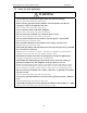
FSP Amplifier Short Form Installation Guide Introduction 1.2. Notes for Safe Operation WARNING • Never touch any rotating motor parts while the motor is running. Failure to observe this warning may result in injury. • Before starting operation with a machine connected, make sure that an emergency stop can be applied at any time. Failure to observe this warning may result in injury. • Never touch the inside of the FS P Amplifier. Failure to observe this warning may result in electric shock.
FSP Amplifier Short Form Installation Guide Introduction WARNING • Do not damage, press and exert excessive force or place heavy objects on the cables. Failure to observe this warning may result in electric shock, stoppage of operation, or burning. • Do not modify the product. Failure to observe this warning may result in injury or damage to the product. • Provide an appropriate stopping device on the machine side to ensure safety.
FSP Amplifier Short Form Installation Guide • Introduction Do not hold the product by the cables or motor shaft while transporting it. Failure to observe this caution may result in injury or malfunction. • Do not place any load exceeding the limit specified on the packing box. Failure to observe this caution may result in injury or malfunction. • Do not hold the product by the eyebolt of motor while transporting it. Failure to observe this caution may result in injury or malfunction.
FSP Amplifier Short Form Installation Guide Introduction Wiring CAUTION • Do not connect a three-phase power supply to the U, V, or W output terminals. Failure to observe this caution may result in injury or fire. • • • S ecurely connect the power supply terminal screws and motor output terminal screws. Failure to observe this caution may result in fire. Do not bundle or run power and signal lines together in the same duct. Keep power and signal lines separated by at least 30 cm (11.81 in).
FSP Amplifier Short Form Installation Guide Introduction CAUTION • Take appropriate and sufficient countermeasures for each when installing systems in the following locations. Failure to observe this caution may result in damage to the product. Locations subject to static electricity or other forms of noise. Locations subject to strong electromagnetic fields and magnetic fields. Locations subject to possible exposure to radioactivity. Locations close to power supplies.
FSP Amplifier Short Form Installation Guide Introduction Maintenance and Inspection CAUTION • Do not disassemble the FS P Amplifier. Failure to observe this caution may result in electric shock or injury. • Do not attempt to change wiring while the power is ON. Failure to observe this caution may result in electric shock or injury. • When replacing the FS P Amplifier, resume operation only after transferring the previous FS P Amplifier parameters to the new FS P Amplifier.
FSP Amplifier Short Form Installation Guide Introduction 1.3. Warning Label The following illustration shows an example of the FSP Amplifier’s warning label. The mounting position of the label differs depending on the model and capacity of the FSP Amplifier.
FSP Amplifier Short Form Installation Guide Introduction 1.4.
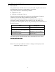
FSP Amplifier Short Form Installation Guide 2. Checking Products On Delivery Checking Products On Delivery The following procedure is used to check FSP- series products upon delivery. Check Item Comments Are the delivered products the ones you ordered? Check the model numbers marked on the nameplates of the FSP Amplifier. Is there any visible damage? Check the overall appearance and check for damage or scratches that may have occurred during transportation.
FSP Amplifier Short Form Installation Guide 3.
FSP Amplifier Short Form Installation Guide Appearance and Nameplate 3.1. Type Designation FSP - 05 D - MC Options - No options C - P re-load ed ECA M S - S ingl e-phas e a mpli fier (08 and 15 only ) Fl exib le S er voPack Max. Appli cable Servom otor Power (s ee table below) Input Voltage B - 100VAC , or A - 200VAC , or D - 400VAC Control Method MC - Serial MH - A-B quadrature Output Capacity Code Max. Applicable S ervomotor Power (kW) A3 A5 01 02 04 05 08 10 15 20 30 50 0.03 0.05 0.10 0.20 0.
FSP Amplifier Short Form Installation Guide 4. Installation Installation The FSP Amplifier is a base-mount type servo controller. Incorrect installation will cause problems. Always observe the installation instructions provided below. 4.1.
FSP Amplifier Short Form Installation Guide Installation 4.3. Orientation Install the FSP Amplifier perpendicular to the wall and orientate it as shown in the figure below. Firmly secure the FSP Amplifier through two or four mounting holes (depending on the FSP Amplifier capacity).
FSP Amplifier Short Form Installation Guide Installation 4.4. Multiple FSP Amplifier Installation FAN C N 3 C N 3 C N 3 C N 1 C N 1 C N 1 C N 1 C N 2 C N 2 C N 2 C N 2 50mm(2in.) or more C N 3 10mm(0.4in.)or more 30mm(1.2in.)or more or more FAN 50mm(2in.) When installing multiple FSP Amplifiers side by side in a control panel, observe the following: 30mm(1.2in.)or more 4.4.1 Where Mounted Side by Side When installing FSP Amplifiers side by side, provide at least 10 mm (0.
FSP Amplifier Short Form Installation Guide 5. Wiring Wiring 5.1. Molded-case Circuit Breaker and Fuse Capacity Current Capacity of the Molded-case Circuit Breaker and the Fuse (Arms)*1, *2 Main Control circuit circuit Power Power Supply Supply Capacity (kW) FSP- Power Supply Capacity per FSP Amplifier (kVA) 0.03 0.05 0.10 0.20 0.03 0.05 0.10 0.20 0.40 A3B* A5B* 01B* 02B* A3A* A5A* 01A* 02A* 04A* 0.15 0.25 0.40 0.60 0.20 0.25 0.40 0.75 1.2 8 Singlephase 220V 0.75 08A* 2.1 11 1.50 15A* 4.
FSP Amplifier Short Form Installation Guide Wiring 5.3. Main Circuit Wire Size Cable Types S ymbol PVC IV HIV • • • • • • Allowable Conductor Temperature ºC (ºF) Cable Types Name Normal vinyl cable — 600V vinyl cable 60 (140) Temperature-resistant vinyl cable 75 (167) Wire sizes are selected for three cables per bundle at 40°C (104°F) ambient temperature with the rated current. Use cable with a minimum withstand voltage of 600V for main circuits.
FSP Amplifier Short Form Installation Guide Wiring Main Circuit Input Terminals (L1, L2, L3), Servomotor Connection Terminals (U, V, W) Main Circuit Power Supply Singlephase 100V Singlephase 200V Singlephase 220V Threephase 200V Threephase 400V Model Capacity (kW) FSP0.03 0.05 0.10 0.20 0.03 0.05 0.10 0.20 0.40 A3B* A5B* 01B* 02B* A3A* A5A* 01A* 02A* 04A* 0.75 08A* 1.50 15A* 2.00 20A* 3.00 0.50 1.00 1.50 2.00 3.00 5.
FSP Amplifier Short Form Installation Guide Wiring Control Power Input Terminals (L1C, L2C), External Regenerative Resistor Terminals (B1, B2) Main Circuit Power Supply Singlephase 100V Singlephase 200V Singlephase 220V Threephase 200V Threephase 400V Model Capacity (kW) FSP0.03 0.05 0.10 0.20 0.03 0.05 0.10 0.20 0.40 A3B* A5B* 01B* 02B* A3A* A5A* 01A* 02A* 04A* 0.75 08A* 1.50 15A* 2.00 20A* 3.00 0.50 1.00 1.50 2.00 3.00 5.
FSP Amplifier Short Form Installation Guide • Ground Terminal Main Circuit Power Supply Singlephase 100V Singlephase 200V Singlephase 220V Threephase 200V Threephase 400V • Wiring Capacity (kW) Model FSP- 0.03 0.05 0.10 0.20 0.03 0.05 0.10 0.20 0.40 0.75 A3B* A5B* 01B* 02B* A3A* A5A* 01A* 02A* 04A* 08A* 1.50 15A* 2.00 20A* 3.00 30A* 0.50 1.00 1.50 2.00 3.00 5.00 05D* 10D* 15D* 20D* 30D* 50D* Ground Terminal Wire Type & Terminal Size Screw (mm2 ) Size Tightening Torque (N·m) HIV 2.
FSP Amplifier Short Form Installation Guide Wiring 5.4. Typical Main Circuit Wiring Examples Only qualified personnel should perform the wiring. Design the circuit so that the main circuit power supply turns OFF at emergency stop. 5.4.1. Single-phase 100V/200V Main Circuit FSP Amplifier 1QF : M olded-case circuit breaker FIL : Noise filter 1KM : M agnetic contactor 1Ry : 1PL : 1SUP : 1D : Relay Indicator lamp Surge suppressor Flywheel diode *1. T hese circuits are power lines.
FSP Amplifier Short Form Installation Guide 5.4.2. Wiring Single-phase 200V 0.8kW and 1.5kW Main Circuit FSP Amplifier 1QF : M olded-case circuit breaker FIL : Noise filter 1KM : M agnetic contactor 1Ry : 1PL : 1SUP : 1D : Relay Indicator lamp Surge suppressor Flywheel diode *1. T hese circuits are power lines. Do not touch these terminals when the power is ON to avoid electric shock. *2. T hese circuits are SELV circuits and are separated from all other circuits by double and reinforced insulation.
FSP Amplifier Short Form Installation Guide 5.4.3. Wiring Three-phase 200V Main Circuit FSP Amplifier 1QF : M olded-case circuit breaker FIL : Noise filter 1KM : M agnetic contactor 1Ry : 1PL : 1SUP : 1D : Relay Indicator lamp Surge suppressor Flywheel diode *1. T hese circuits are power lines. Do not touch these terminals when the power is ON to avoid electric shock. *2. T hese circuits are SELV circuits and are separated from all other circuits by double and reinforced insulation.
FSP Amplifier Short Form Installation Guide 5.4.4. Wiring Three-phase 400V Main Circuit FSP Amplifier 1QF : M olded-case circuit breaker FIL : Noise filter 1KM : M agnetic contactor 1Ry : 1PL : 1SUP : 1D : Relay Indicator lamp Surge suppressor Flywheel diode *1. T hese circuits are power lines. Do not touch these terminals when the power is ON to avoid electric shock. *2. T hese circuits are SELV circuits and are separated from all other circuits by double and reinforced insulation.
FSP Amplifier Short Form Installation Guide Wiring 5.5. Main Circuit Wiring Graphic Diagrams 5.5.1. Single-phase 100V/200V Main Circuit Personal Computer Cable type P/N: YS-12 Host Controller FSP Amplifier is compatible with most PLC motion controllers and indexers. Used for a servomotor with a brake.
FSP Amplifier Short Form Installation Guide 5.5.2. Wiring Single-phase 200V 0.8kW and 1.5kW Main Circuit Observe the following points. 1. Connect main power supply shown below to L1 and L3 terminals. Power supply is single-phase, 220 to 230VAC +10% to -15%, 50/60Hz. If power supply of 187 V (-15% of 220V) or less is used, alarm A.41 indicating voltage shortage, may occur when accelerating to max speed with max torque of motor. 2. Short-circuit B2 and B3 terminals using the internal regenerative resistor.
FSP Amplifier Short Form Installation Guide 5.5.3. Wiring Three-phase 200V Main Circuit Personal Computer Cable type: P/N YS-12 Host controller FSP Amplifier is compatible with most PLC motion controllers and indexers. Used for a servomotor with a brake.
FSP Amplifier Short Form Installation Guide 5.5.4. Wiring Three-phase 400V Main Circuit Personal computer Cable type: P/N YS-12 Host controller FSP Amplifier is compatible with most PLC motion controllers and indexers. Used for a servomotor with a brake.
FSP Amplifier Short Form Installation Guide • • • • • • Wiring In conformance with local electrical codes, ground the FSP Amplifier grounding terminal (grounding resistance: 100 Ω or less). Be sure to connect the grounding wire of the servomotor to of the FSP Amplifier. Never share the grounding cable or main grounding point with welding equipment, power equipment or other high-voltage devices. Separate the grounding cable from wiring of high-voltage equipment.
FSP Amplifier Short Form Installation Guide Wiring 5.6. AC Power Source Supply Use the FSP Amplifier AC power source supply according to product ratings. See the following table for details. Power SinglePhase 200V ThreePhase 200V ThreePhase 400V FS P Amplifier Motor Output FSP-A3A* to FSP-04A* 30, 50, 100, 200, and 400W FSP-08A* and FSP-15A* 750 W and 1.5kW FSP-10A* to FSP-30A* 1.0, 2.0, and 3.0kW FSP-05D* to FSP-50D* 0.5, 1.0, 1.5, 2.0, 3.0 and 5.
FSP Amplifier Short Form Installation Guide 6. Operation Operation This section describes precautions that should be taken at test run and during operation. For instructions on test run and operation, refer to the Sigma FSP Servo System User’s M anual (Document # YEA-SIA-FSP-3). 6.1. Precautions at Test Run CAUTION • To avoid accidents, run the servomotor only in test run (without load). Failure to observe this caution could result in personal injury.
FSP Amplifier Short Form Installation Guide Operation 6.4. Precautions During Operation CAUTION • During operation, do not touch the FS P Amplifier's heat sink. Failure to observe this caution could result in burns. • Motor overload protection is provided internally. Refer to the S igma FS P S ervo S ystem User’s Manual (Document # YEA-S IA-FS P-3) for rating.
FSP Amplifier Short Form Installation Guide 7. Inspection and Maintenance Inspection and Maintenance This section describes the basic inspection and maintenance procedures for the FSP Amplifier and battery replacement for absolute encoder. If any failure occurs on the FSP Amplifier, refer to the Sigma FSP Servo System User’s M anual (Document # YEA-SIA-FSP-3), Troubleshooting. Contact your YEA representative if the problem persists. WARNING • Be sure to turn OFF power before inspection or maintenance.
FSP Amplifier Short Form Installation Guide Inspection and Maintenance 7.2. Part Replacement Period The following parts are subject to mechanical wear or deterioration over time. To avoid failure, replace these parts at the frequency indicated. If the FSP Amplifier has been repaired at YEA, its parameters will be set back to standard settings at shipment. Always check parameters before operating the servomotor.
FSP Amplifier Short Form Installation Guide 7.3.2. Inspection and Maintenance Replacing the Battery 1. With the FSP Amplifier's control power turned ON, replace the old battery with a new one. 2. Turn OFF the FSP Amplifier's control power to clear the absolute encoder battery alarm (A.83). 3. Turn ON the FSP Amplifier's control power. 4. M ake sure that FSP Amplifier is operating normally after power is turned on. Battery replacement is now completed.
FSP Amplifier Short Form Installation Guide 8. Installation Conditions of EMC Directive Installation Conditions of EMC Directive The following conditions must be satisfied for a combination of servomotor and the FSP Amplifier to comply with EM C Directives (EN61000-6-2 and EN55011, Group 1 Class A). 8.1. EMC Installation Conditions This section describes the test installation conditions prepared by YEA that meet EM C guidelines for all FSP Amplifier models.
FSP Amplifier Short Form Installation Guide 8.1.2. Installation Conditions of EMC Directive Installation: Single & Three-phase 100/200V FSP Amplifier (PLC) FSP-A3A* to -30A*(30W to 3.0kW) Represents option with PLC or controller connected to CN1 connector. Note: S hielded Box with door closed Cable length approx. 5m Brake Power Supply CORE NOISE FILTER Mains Cable Length Approx.
FSP Amplifier Short Form Installation Guide 8.1.3. Installation Conditions of EMC Directive Installation: Three-phase 400 V FSP Amplifier FSP-10D* to -30D* (0.5 kW to 3.0 kW) Represents option with PLC or controller connected to CN1 connector or PC connected to CN3 connector. Note: S hielded Box with door closed Cable length approx.
FSP Amplifier Short Form Installation Guide Installation Conditions of EMC Directive 8.2. Cable Core and Cable Clamp 8.2.1. Cable Core Attach the core on the cable as shown in the diagram below, which shows two turns of the cable: Cable Core The table below lists the cable names and the mounting positions of the core: Cable Name 8.2.2. Core Mounting Position Controller cable Near the Controller and the FSP Amplifier. Servomotor cable Near the FSP Amplifier and the servomotor.
FSP Amplifier Short Form Installation Guide 9. Peripheral Devices Peripheral Devices 9.1. Peripheral Device Types and Capacities The following table gives examples of peripheral devices for use with Yaskawa or other compatible motors. Main Model Circuit Power Supply Capacity FSP(kW) 0.10 A3B * A5B * 01B * 0.20 02B * 0.03 Singlephase 100 V 0.05 0.03 0.05 Singlephase 200 V 0.10 0.20 0.40 0.75 1.5 Threephase 200 V 1.0 2.0 3.0 0.45 1.0 Threephase 400 V 1.5 2.0 3.0 5.
FSP Amplifier Short Form Installation Guide Peripheral Devices Circuit Filter model Manufacturer Brake power circuit FN2070-6/X*3 or FMW2-52-6/07 Schaffner or Timonta *3 Replace X with connection type: 07 = wire, 06 = for soldering or fast-on.
FSP Amplifier Short Form Installation Guide Peripheral Devices 9.3. Cable Specifications Shield cables should be used for the following cables: • • • • AC power input line cable (between power supply and noise filter) Servomotor cable (between FSP Amplifier and servomotor) Encoder cable (between FSP Amplifier and servomotor) Controller cable (between FSP Amplifier and controller) 9.4. Recommended Ferrite Cores Cable Manufacturer Encoder Cable Absolute Power Cable Serial 30W to 400W 0.
FSP Amplifier Short Form Installation Guide Overload Characteristics 10. Overload Characteristics The FSP Amplifier has a built-in overload protective function that protects the amplifier-motor pair from overload. Allowable power for the FSP Amplifier is limited by the overload protective function as shown in the figure below. The overload detection level is set under hot start* conditions at a servomotor ambient temperature of 40ºC (104ºF).
FSP Amplifier Short Form Installation Guide Appendix A 11. Appendix A 11.1. I/O Signals Connector CN1 CN1 connector is required to connect the host controller to the FSP Amplifier. It comprised of a connector and a connector cover. Mating 50-Pin Connector Model (Kit) YEA P/N Connector Connector Parts 10150-3000VE * 4J4003 Case 10350-52A0-008 * * M anufactured by Sumitomo 3M Co. Terminal Layout Pin No. Name Pin No.
FSP Amplifier Short Form Installation Guide Appendix A 11.2. Encoder Connector CN2 Mating 20-Pin Connector Model Connector YEA P/N Connector Parts 4J4001 10120-3000VE* 4J0101 Cover * M anufactured by Sumitomo 3M Co. 10320 - 52A0-008* Terminal Layout Pin No. 1 2 3 4 5 6 7 8 9 10 Name Pin No.
FSP Amplifier Short Form Installation Guide Appendix A 11.3. Serial Communication Connector CN3 Mating 14-Pin Connector Model YEA P/N 4J4002 Connector Parts 10114-3000VE* Connector 4J0102 Cover * M anufactured by Sumitomo 3M Co. 10314-52A0-008* Terminal Layout Pin No. Name Pin No. 1 2 3 4 5 6 7 T XD /T XD RXD /RXD NC* /RXD RT (termination resistor) 8 9 10 11 12 13 14 Name T XD /T XD RXD NC* NC* +5V GND Note: NC – Leave contact open (Not Connected) 11.4.
FSP Amplifier Short Form Installation Guide Appendix A 11.5.
FSP Amplifier Short Form Installation Guide Appendix A 11.6.
FSP Amplifier Short Form Installation Guide Appendix A 57
FSP Amplifier Short Form Installation Guide Appendix A Yaskawa Electric America, Inc. 2121 Norman Drive South Waukegan, IL 60085 United States Tel: 1-800-927-5292 Fax: 1-847-887-7310 motionproducts@yaskawa.com For more information refer to our web site: www.yaskawa.com Specifications are subject to change without notice due to ongoing product modifications and improvements. YEA-SIA-FSP-2 Rev.