
Instruction manual


5. Operating the Inverter
47
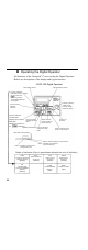
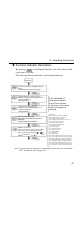
Function Indicator Description
By pressing on the Digital Operator, each of the function indi-
cators can be selected.
The following flowchart describes each function indicator.
Note: The unit used for frequency is determined by the value set for constant
n035. For details, refer to page 196.
Power ON
Frequency reference setting/monitoring
(r/min)
Sets Varispeed V7 operating speed.
Output frequency monitoring (r/min)
Displays frequency that Varispeed V7 is
currently outputting
Setting disabled.
Output current monitoring (A)
Displays current that Varispeed V7 is
currently outputting
Setting disabled.
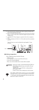
(forward run) (reverse run)
If the Varispeed V7
loses power while in
one of these modes,
it will return to the same
mode once power is
restored.
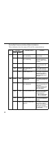
Monitor No.
U-01: Frequency reference (FREF)
U-02: Output frequency (FOUT)
U-03: Output current (IOUT)
U-04: Output voltage reference (Unit: 1V)
U-05: DC voltage (Unit: 1V)
U-06: Input terminal status
U-07: Output terminal status
U-08: Torque monitor
U-09: Fault history
U-10: Software number
U-11: Output power
U-16: PID feedback
U-17: PID input
U-18: PID output
U-60: DeviceNet produced connection path
U-61: DeviceNet consumed connection path
U-62: MAC ID Setting (on Rotary Switches)
U-63: MAC ID Setting (during operation)
U-64: Baud Rate Setting (on Rotary Switch)
U-65: Baud Rate Setting (during operation)
U-66: DeviceNet Connection instance status
U-70: Frequency reference from DeviceNet
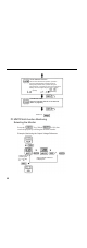
FWD/REV run selection
Sets the motor rotation direction when the RUN
command is given from the Digital Operator.
Setting can be changed using the or key.
Multi-function monitoring
Description of the selected monitor is
displayed.
(Refer to page 49 for details.)