
User`s manual


4 Installation and Wiring
15
4 Installation and Wiring
Route the MECHATROLINK communications cables separately from the main circuit wiring and
other power lines.
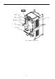
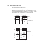
4.1 Installing the SI-T Card
Use the following procedure to mount the SI-T Card after removing the Inverter’s Digital
Operator and front cover.
1. Turn OFF the Inverter’s main-circuit power supply.
2. Confirm that all the indicators on the Inverter have turned OFF, wait until the specified
period of time has elapsed (the time is shown on the Inverter’s front cover), and then
remove the Digital Operator and the front cover. Verify that the CHARGE lamp is unlit.
3. Remove the Option Clip (the clip to secure option C or D) on the Inverter. The Clip can
be easily pulled out by pinching its projections.
4. Install the SI-T Card on the option C connector 2CN (60 pins) on the Inverter control
board. Secure the Card by inserting the spacers on the control board into the spacer
mounting holes (three holes) of the Card until hearing a “click.” (Refer to A in Fig.1.)
Note: The SI-T Card (option C) and option D cannot be used at the same
time.
5. Insert the Option Clip to its original position.
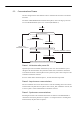
6. Connect the Card grounding cable to the control circuit terminal E (G) on the Inverter
control board.
7. After the Card is installed, connect the communications cables and set the DIP switches.
(Refer to 3.4 and 4.2.)
8. Remount the Digital Operator and the front cover.
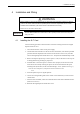
• Before installing or removing the Option Card, or performing wiring operations, always turn OFF the
power to the Inverter and wait until the specified period of time has elapsed after all the Inverter
indicators have turned OFF. (The time is shown on the Inverter’s front cover.)
Failure to do so can result in electric shock.
WARNING
IMPORTANT