
Specifications


5 Wiring
13
5.2 Wiring Precautions
Make sure of the following when wiring.
• Separate the control signal wires (terminal blocks TA1 and TA2) of the PG-X2 card from the main
circuit wires and other power cables.
• Use a shielded wire to connect the encoder (PG). Connect the wires as shown in Fig. 5 to prevent
noise interference. The wire distance must be 328 ft. (100 m) or less.
• To prevent noise, use shielded wire and separate from heavy current circuits (200 VAC or greater)
or relay drive circuits. (Wire length to the PG connector must be 328 ft. (100 m) or less.)
• If the PG signal is affected by noise, disconnect the grounding lead wire (E) from the grounding
terminal (G5: 12 (G), G7 or F7: E (G)) of the control board of the Inverter. Alternatively, change
the location of the shielded sheath connection.
• The recommended tightening torque is 0.22 to 0.25 Nxm.
Fig. 5 Shielded Wire Termination
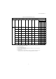
Applicable wire specifications for terminal blocks TA1 and TA2 are shown in Table 2.
Terminal: MKDS1 series manufactured by Phoenix Contact GmbH & Co.
NOTE
Outer Jacket
Shielded Sheath
Connect to terminal block
TA3 on PG-X2 card
Do not connect
or ground sheild at
this end
Insulate these parts
with insulting tape
PG-X2 Connection
Encoder (PG) End
Table 2 Wire Specifications
(mm
2
)
AWG I (amps) VAC
Thin Twisted Wire
1 16 12 125
Solid Wire
1.5 16 12 125
UL
− 22-16 10 300
CSA
− 28-16 10 300
CSA
− 28-16 10 150