
Specifications


16
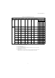
7 PG-X2 Card Parameter List
If using the PG-B2 card with any Yaskawa drives other than the G5, F7, or G7, refer to the
instruction manual of the drive being used.
Table 3 PG-X2 Card Parameter List
PG-X2 Card Parameter List
Digital
Operator
Function
Group
Digital
Operator
Display
Param-
eter
No.
Parameter
Name
Setting
Range
Factory
Setting
Change
During
Opera-
tion
*1
Data Selection
Control Method
*2
G5, G7, F7 G7
V/f Control
V/f w/PG Fdbk
Open loop Vector
Flux Vector
*9
Open loop Vector 2
PG
Option
Setup
PG Pulses/
Rev
F1-01 PG constant 0 to 60000 600
××{ × { ×
PG Fdbk
Loss Sel
F1-02 Operation
selection at PG
open circuit
(PGO)
0 to 3 1
×
0: Ramp to Stop
1: Coast to Stop
2 : F a s t - S t o p
3: Alarm Only
× { × { ×
PG Over-
speed Sel
F1-03 Operation
selection at
overspeed (OS)
0 to 3 1
××{ × {{
PG Devia-
tion Sel
F1-04 Operation
selection at
deviation
0 to 3 3
××{ × {{
PG Rotation
Sel
F1-05 PG rotation 0,1 0
×
0 : F w d = C C W
1: Fwd=CW
× { × { ×
PG Output
Ratio
F1-06 PG division rate 1 to 132 1
×
Effective with
PG-B
× { × { ×
PG Ramp PI/
I Sel
F1-07 Integral value
during accel/
decel enable/
disable
0,1 0
×
0: Disabled
1: Enable
× { ×××
PG Overspd
Level
F1-08 Overspeed
detection level
0 to 120 % 115 %
××{ × {{
PG Overspd
Time
F1-09 Overspeed
detection delay-
time
0 to 2.0 s
0.0 s
*3
(1.0 s)
*4
××{ × {{
PG Deviate
Level
F1-10 Excessive speed
deviation detec-
tion level
0 to 50 % 10 %
××{ × {{
PG Deviate
Time
F1-11 Excessive speed
deviation detec-
tion delay time
0 to 10 s 0.5 s
××{ × {{
PG# Gear
Teeth 1
F1-12 Number of PG
gear teeth 1
0 to 1000 0
××{ ×××
PG# Gear
Teeth 2
F1-13 Number of PG
gear teeth 2
0 to 1000 0
××{ ×××
PGO Detect
Time
*5
F1-14 PG open-cir-
cuit detection
time
0 to 10 s 2 s
××{ × { ×