YASKAWA Varispeed G7/F7 OPTION CARD CC-Link COMMUNICATIONS INTERFACE CARD USER'S MANUAL Model: SI-C YASKAWA MANUAL NO.
Copyright © 2006 YASKAWA ELECTRIC CORPORATION All rights reserved. No part of this publication may be reproduced, stored in a retrieval system, or transmitted, in any form, or by any means, mechanical, electronic, photocopying, recording, or otherwise, without the prior written permission of Yaskawa. No patent liability is assumed with respect to the use of the information contained herein.
INTRODUCTION INTRODUCTION This User's Manual describes the operations and specifications of the CC-Link Communications Interface Card (hereafter called the SI-C card). The SI-C card transfers the data between the Varispeed series Intelligent Vector Control General-Purpose Drive and the MITSUBISHI FA Field Network CC-Link (hereafter called the CC-Link). Read this manual carefully and be sure you understand the information provided before attempting any operations.
SAFETY INFORMATION Read this instruction manual thoroughly before installation, operation, maintenance or inspection of the CC-Link Communications Interface Card SI-C. In this manual, NOTES FOR SAFE OPERATION are classified as “WARNING” and “CAUTION.” WARNING CAUTION Even items described in Indicates a potentially hazardous situation which, if not avoided, could result in death or serious injury to personnel.
SAFETY INFORMATION Installation and Wiring WARNING Never touch the inside of the Inverter. Failure to observe this warning may result in electric shock. Disconnect all power before mounting or removing the option card or wiring. Then wait at least the specified time (specified on the front cover) after the power supply is disconnected and all LEDs and CHARGE LED are extinguished. Failure to observe this warning may result in electric shock. Do not damage or apply excessive stress to the cables.
Contents INTRODUCTION········································································································· 3 SAFETY INFORMATION ···························································································· 4 1 OUTLINE ································································································ 7 2 RECEIVING ···························································································· 8 3 NOMENCLATURE AND SETTING··························
1 OUTLINE 1 OUTLINE The SI-C card is an interface card to achieve data communications with the CC-Link master for connecting the Varispeed series Intelligent Vector Control Inverter to the MITSUBISHI FA Field Network CC-Link. The SI-C card is conforming to the CC-Link version 1.10.
2 RECEIVING Check the following items as soon as the product is delivered. Item Method Has the correct model of the SI-C card been delivered? Compare the model number on your order to the number printed in the lower right corner of the SI-C card. (Refer to 3.1.) Is the SI-C card damaged in any way? Inspect the entire exterior of the SI-C card to see if there are any scratches or any other damage resulting from shipping.
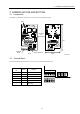
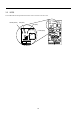
3 NOMENCLATURE AND SETTING 3 NOMENCLATURE AND SETTING 3.1 Components The names of components on the SI-C card are shown in the following figure. LED Connector for Maintenance 105 60 Terminal Block Rotary Switches Front Back Unit: mm 3.2 Terminal Block This terminal block connects the SI-C card to the CC-Link communications line.
3.3 LEDS These LED indicator lamps indicate the status of the CC-Link or the SI-C card. L.RUN (Green) RD (Red) SD (Red) L.
3 NOMENCLATURE AND SETTING LED display L.RUN SD RD L.ERR (Green) (Red) (Red) (Red) * Meaning :Blinking :Not lit Corrective action Normal but an error is occurring. Normal Remove the influence of noise. Normal Normal — H/W error CALL or BUS Turn the power supply OFF and then ON again. H/W error CALL or BUS Turn the power supply OFF and then ON again. A CRC error occurred, and the SI-C card cannot reply. Normal Remove the influence of noise. Local data cannot be received.
3.4 Rotary Switches Use these switches to set the baud rate and the station number of the CC-Link. 23 23 901 901 23 456 78 456 78 78 45 6 9 01 B RATE STA ×10 STA ×1 Baud rate setting Station No. setting 2nd digit Station No. setting 1st digit Before turning ON the inverter's power supply, set these three switches. Do not change the NOTE settings after turning ON the power supply. Be sure to change the settings after turning OFF the inverter power supply. 3.4.
3 NOMENCLATURE AND SETTING 2. The station number cannot be overlapped. Confirm that the station number has not been set for any other stations. 3. The maximum number of stations to be connected is 42 when the following conditions are satisfied.
4 INSTALLATION AND WIRING 4.1 Installing the SI-C Card Install the SI-C card is where the operator and the front cover of the Inverter are removed. Use the following procedure to install the SI-C card. 1. Turn off the main-circuit power supply. 2. Wait one minute (three minutes when using an Inverter whose motor capacity is more than 30kW) before removing the operator and the front cover of the Inverter. Confirm that the CHARGE indicator is OFF. 3.
4 INSTALLATION AND WIRING NOTE When installing the SI-C card, handle it by the edges to prevent damaging the card. 4.2 Wiring of the Communications Cable 4.2.1 Wiring Use the following procedure to wire the CC-Link master to the terminal block of the SI-C card. 1. Use a thin flat screwdriver to loosen the terminal screw. 2. Insert the wires from under the terminal block. 3. Tighten the terminal screws firmly. (Tightening torque: 0.22 to 0.25 [N m]) Terminal Block Sheath strip: Cable approx. 5.
4.2.2 Communication Cable Specifications Be sure to use a cable with the following specifications as the communications cable. Any cable other than recommended cable shown below cannot assure the performance of the CC-Link. Item Specifications 2 Model FANC-SB 0.5 mm ×3 [Manufactured by Kuramo Electric Co., Ltd] Conductor cross-sectional area 0.5 mm2 Conductor resistance (at 20°C) 37.
4 INSTALLATION AND WIRING 4.2.4 Wiring and Connecting the CC-Link Master Unit Figure-2 and Figure-3 show how the CC-Link master unit is connected. M 3-Phase AC200~230V DRIVE DA DA DB DB CC Link DC Master Unit SLD DC SLD SLD SLD FG NOTE: NOTE SI-C FG Disconnect the ground wire when communication errors occur as a result of noise.
5 FUNCTIONS The SI-C card is a communications interface card for operations, adjustments, and monitoring using the PLC program with the Varispeed Series as a remote device station for the CC-Link. Both bit data and word data cyclic transmissions are available, and high-speed communications up to 10 Mbps are possible. 5.1 Initial Settings Set the following parameters whenever necessary, before starting communications between the Inverter and the PLC.
5 FUNCTIONS 5.2 Basic Functions The section describes the basic functions that can be done from the PLC using the CC-Link communications function. 5.2.1 Run Command and Frequency Reference Running or stopping the inverter, or setting or changing the operation frequencies can be done from the PLC. To perform these operations from the PLC, the right to use the inverter run command and the frquency references must be assigned to the inverter to the PLC side.
Frequency Reference Rights Setting Status Local/Remote Selection b1-01 (Reference selection) Local Remote Remote Remote — 3 All others excluding 3 Option/Inverter Selection — — ON Option (communications) Frequency Reference Right Inverter PLC PLC All others excluding 3 OFF Inverter Depends on the setting of b1-01. Note: 1 When a multi-step speed reference for the multi-function input is received, the multi-step speed references, d1-01 to d1-09, have priority over any other references.
5 FUNCTIONS Remote Output (from PLC to Inverter) Device No.
5.3.2 Details of Remote Inputs and Outputs List of Remote Inputs and Outputs Remote Outputs (from PLC to Inverter) Device No.
5 FUNCTIONS Remote Input (from Inverter to PLC) Signal Name Device No. RX0 Forward run Description ON: Forward run, Remarks (Defaults) — OFF: All others excluding forward run (including DC injection braking) RX1 Reverse run ON: Reverse run, — OFF: All others excluding reverse run (including DC injection braking) Terminals M1-M2 multi-function output Multi-function output 1: (H2-01)*3 RX3 Speed agree ON when the output frequency is between the setting frequency to L4-02 setting.
Changing RY19 Multi-Function I/O Allocation The drive’s multi-function I/O layout will change as shown below when RY19 is switched on or off.
5 FUNCTIONS From the Drive to PLC Remote Register RWR0 Name Monitor data Description Stores the monitor data corresponding to the monitor code of RW R1. While the monitor request flag (RYC) is turned ON, this data are updated and the monitoring signal (RXC) is turned ON. The current output frequency is always set. However, the unit depends on the setting of o1-03 (frequency reference setting/display unit selection). Output frequency RWR1 For example, when o1-03 is set to 0, units appear in Hz.
5.3.3 List of Monitor Codes and Command Codes Monitor Codes First Monitor Code Monitor Code 0000h Name Unit Not used Remarks (Factory Setting) — — o1-03 setting The unit depends on the setting of the o1-03 (frequency reference setting/display unit selection). 0: 0.01Hz (less than 100Hz) : 0.1Hz (100Hz or more) 0001h Output frequency 1: 0.1% 2 to 39: r/min (Sets number of motor poles) 40 to 39999: User Setting 0002h Output current 0.1 A — 0003h Output voltage 0.
5 FUNCTIONS Monitor Code 0010h Name Unit Remarks (Factory Setting) 7 6 5 4 3 - - - - - 2 26 1 25 Output terminal status 0 9 bit RWR3 M1-M2 output status ON:1 P1 output status ON:1 P2 output status ON:1 0011h — 0012h Motor exciting current 0013h — 0014h * Cumulative operation time — — 0.1% Motor rated secondary current: 100% — — Function alternates according to the setting of o2-08 (Comulatve operation time selection).
Command Codes Item Code No. Reading run command right 1181h Reading frequency reference right Writing run command right 1180h 2181h Writing frequency reference right 2180h Data The current run command right is assigned to RWR3. 0: Operator 1: External terminal 2: Memobus 3: PLC 0: Operator 1: External terminal 2: Memobus 3: PLC 0: Operator 1: External terminal 2: Memobus 3: PLC 0: Operator 1: External terminal 2: Memobus 3: PLC The current frequency reference right is assigned to RW R3.
5 FUNCTIONS Extensive Command Codes Command Code Read Name Data/Unit Write 100h ― Operation signal status 101h 102h ― 202h 103h 203h Frequency reference Torque reference/torque limit Torque compensation 104h 105h 204h 205h 106h 206h 107h 207h Not used INV terminal 21 analog output INV terminal 23 analog output INV terminal multi-function output bit 0 Forward run 1 Reverse run 2 Terminal S3 input 3 Terminal S4 input 4 Terminal S5 input 5 Terminal S6 input 6 Terminal S7 input 7 Terminal S
Name Command Code Reading 110h Data/Unit Description Writing — (Cont’d) Inverter status bit (Cont’d) C D E F Terminal P1 output Terminal P2 output Reserved Reserved 111h 112h 113h 114h — — — — Reserved Torque monitor *2 Reserved Operation frequency set value — -300.0% to +300.0% — 0.0Hz to 400.0Hz 115h 116h 117h — — — 0.0Hz to 400.0Hz 0.1A 0.
5 FUNCTIONS Fault Alarm Signals and Currently Occurring Faults Fault Alarm (Command Code) Fault Alarm 1 bit (119H) Fault Alarm 2 (11AH) bit Fault Alarm 3 (11BH) bit Name 0 1 2 3 4 5 6 7 8 9 A B C D E F 0 1 2 3 4 5 6 7 8 9 A B C D E F 0 1 2 3 4 5 6 7 8 9 A B C D E F Fuse blown (PUF) Main circuit undervoltage (UV1) Control power supply fault (UV2) Inrush prevention circuit fault (UV3) Load short-circuit (SC) Ground fault (GF) Overcurrent (OC) Main circuit overvoltage (OV) Cooling fin overheating (OH) C
6 SPECIFICATIONS Item Specifications Model SI-C Station type Remote device station Number of Exclusive Stations 1 station Communications Speed 156kbps to 10Mbps Communication power supply 4.75 to 5.25Vdc (supplied by the drive and insulated from the main power supply) Operating Power Supply 4.75 to 5.25Vdc (supplied from the inverter) Ambient Temperature –10°C to +45°C Humidity 95%RH max.
7 TROUBLESHOOTING 7 TROUBLESHOOTING 7.1 Inverter Errors The following table outlines the faults displayed in the Drive’s operator and their causes and corrective actions. Refer to the Drive instruction manual for any faults displayed in the operator other than those described below.
7.2 CC-Link Interface Card LEDs This section describes the failures, causes, and corrective actions indicated by the LEDs on the SI-C card. Confirm the following when communications are halted during operation. • The SI-C card and the twisted pair cable are attached correctly. Check that there is no faulty contact or disconnection. • The PLC program has been executed without a failure. The PLC CPU has not been stopped.
7 TROUBLESHOOTING The following table describes the failures, causes, and corrective actions that can be judged according to the LED of the inverter CC-Link unit (SI-C unit) when the LED display of the master unit SW, M/S or PRM has been extinguished (always set in the master unit), in the system configuration shown below. Power CPU Master Unit Station Station Station No. 1 No. 2 No. 3 Inverter Inverter Inverter LED Display Master Unit Remote Device Station(SI-C) Station No. 1 L.RUN SD RD L.
How to check an error indicated by the LEDs. L.RUN: Lit when the refleshed data is successfully received. Extinguished if data communications are interrupted for a specified period of time. SD : Lit when sending data is "1". RD : Lit when detecting the receiving data carrier. L.ERR: Lit when the local data has a CRC abort error.
7 TROUBLESHOOTING LED Display L.RUN SD RD Meaning L.ERR Corrective Actions A CRC error occurred in local data. Remove the influence of noise. Local data is not provided or cannot be received because of noise. Remove the influence of noise. Hardware error Turn the power supply OFF and then ON again. Data cannot be received because of a disconnection. Check the wiring. Baud rate or station number is not correct. Correct the setting and turn the power supply OFF and then ON again.
8 APPENDIX 8.1 List of Command Code Registers 8.1.
8 APPENDIX 8.1.2 Status Data (read only) Command Code Read Write 1010H - 1011H - 1012H 1013H - 1014H - 1015H - Description BIT Display Drive Status 0 1: During Run 1 1: Zero Speed 2 1: While in REV 3 1: Reset Signal During Input 4 1: During Speed Agree 5 1: Drive Ready 6 1: Alarm 7 1: Fault 8-D Not Used E 1: Comref Status F 1: Comctrl Status Operator Status 0 1: During OPE 1 Not Used 2 1: PRG mode 3-F Not Used Openo.
Command Code Read Write 1016H - Description BIT Display Fault Description 3 0 CE Memobus Communication Error 1 BUS Option Communication Error 2 Not Used 3 Not Used 4 CF Control Fault 5 Not Used 6 EFO External Fault Input from Communication Card 7 FBL PID Feedback Command Loss 8 UL3 Undertorque Detection 1 9 A B-E 1017H - 1018H - 1019H - UL4 Undertorque Detection 2 OL7 High Slip Braking OL - Not Used F CPF Hardware Fault CPF Description 1 0 Not Used 1 Not Used 2 During CPF02 3 During CPF03 4 Duri
8 APPENDIX Command Code Read Write 101AH - 1020H - 1021H - 1022H - Description BIT Display Alarm Description 2 0 DEV Excessive Speed Deviation 1 PGO PG Disconnect Detection 2 OPR Digital Operator Connection Error 3 CE Memobus Communication Error 4 BUS Option Card Communication Error 5 CALL Waiting for Data via Communications 6 OL1 Motor Overload 7 OL2 Inverter Overload 8 Not Used 9 EFO During Comm.
Command Code Read Write 1023H 1024H 1025H 1026H 1027H 1028H 1029H 102AH - 102BH - 102CH - 102DH - Description BIT Display Frequency Reference (U1-01) Output Frequency (U1-02) Output Voltage Command (U1-06) Output Current (U1-03) Output Power (U1-08) Torque Reference (U1-09) Not Used Not Used Sequence Input Status 0 1: Multi-Function Digital Input Terminal S1 ON 1 1: Multi-Function Digital Input Terminal S2 ON 2 1: Multi-Function Digital Input Terminal S3 ON 3 1: Multi-Function Digital Input Terminal
8 APPENDIX Command Code Read Write 102EH -1030H 1031H 1032H 1033H 1034H -1037H 1038H 1039H 103AH 103BH 103CH - 103DH - 103EH 103FH - Description BIT Display Not Used Main Circuit DC Voltage Torque Monitor Output Power Not Used PID Feedback Amount PID Input Amount PID Output Amount Software Number (CPU) Software Number (Flash) Comm.
8.1.3 Monitor Data (read only) For more details, refer to the instruction manual. The digital operator displays the same units as the monitor, with the exception of the units for the output current and frequency related units.
8 APPENDIX Command Code Read Write 1051H 1052H - BIT U1-18 Motor Secondary Current (Iq) U1-19 Motor Excitation Current (Id) Description 1053H 1054H 1055H 1056H 1057H 1058H 1059H 105AH 105BH 105DH 105EH 105FH 1060H 1061H 1062H 1063H 1064H 1065H - U1-20 U1-21 U1-22 U1-24 U1-26 U1-27 U1-28 U1-32 U1-33 U1-34 U1-35 U1-36 U1-37 U1-38 1066H - U1-39 1067H 1069H 106AH 106BH 106CH - U1-40 U1-42 U1-43 U1-44 U1-45 Output Frequency after SFS *2 Speed Control (ASR) Input Speed Control (ASR) Output Not Used P
• U2-xx Monitor Details Command Code Read Write 1080H 1081H 1082H 1083H 1084H 1085H 1086H 1087H 1088H 1089H - • U2-01 U2-02 U2-03 U2-04 U2-05 U2-06 U2-07 U2-08 U2-09 U2-10 108AH - U2-11 108BH - U2-12 108CH - U2-13 108DH - U2-14 Description BIT Current Fault Previous Fault Frequency Reference at Previous Fault Output Frequency at Previous Fault Output Current at Previous Fault Motor Speed at Previous Fault Output Voltage at Previous Fault DC Bus Voltage at Previous Fault Output Power at Previ
8 APPENDIX Fault Codes for U2-01, U2-02, and U3-01 through U3-08: Display PUF UV1 UV2 UV3 GF OC OV OH OH1 OL1 OL2 OL3 OL4 Rr RH EF3 EF4 EF5 EF6 EF7 OS DEV PGO PF LF OPR ERr CE BUS CF EFO FBL Description Fault Code Fuse Blown Main Circuit Undervoltage Control Power Supply Fault Inrush Prevention Circuit Fault Load Short Circuit Ground Overcurrent Overvoltage Heat Sink Overheat Drive Internal Cooling Fan Overheat Motor Overheat Inverter Overload Overtorque 1 Overtorque 2 Internal Braking Transistor Fault
8.1.4 Parameter Data (possible to both read and write data) For more information on the setting range, refer to the users manual for the drive.
8 APPENDIX Command Code Read Write 11B6H 21B6H 11B7H 21B7H 11B8H 21B8H 11B9H 21B9H 11CAH 21CAH 11CBH 21CBH 11CCH 21CCH 11CDH 21CDH 11CEH 21CEH 11CFH 21CFH 11D0H 21D0H 11D1H 21D1H 11DAH 21DAH 11DBH 21DBH 1200H 2200H 1201H 2201H 1202H 2202H 1203H 2203H 1204H 2204H 1205H 2205H 1206H 2206H 1207H 2207H 1208H 2208H 1209H 2209H 120AH 220AH 120BH 220BH 120CH 220CH 120DH 220DH 120EH 220EH 120FH 220FH 1210H 2210H 1211H 2211H 1212H 2212H 1213H 2213H 1215H 2215H 1216H 2216H 121BH 221BH 121CH 221CH 121DH 221DH 121EH 22
Command Code Read Write 1280H 2280H 1281H 2281H 1282H 2282H 1283H 2283H 1284H 2284H 1285H 2285H 1286H 2286H 1287H 2287H 1288H 2288H 128BH 228BH 128CH 228CH 128DH 228DH 128EH 228EH 128FH 228FH 1290H 2290H 1291H 2291H 1292H 2292H 1289H 2289H 128AH 228AH 1293H 2293H 1294H 2294H 1295H 2295H 1296H 2296H 1297H 2297H 1298H 2298H 1299H 2299H 129AH 229AH 129BH 229BH 129CH 229CH 129DH 229DH 129EH 229EH 129FH 229FH 12A0H 22A0H 12A1H 22A1H 12A2H 22A2H Name d1-01 d1-02 d1-03 d1-04 d1-05 d1-06 d1-07 d1-08 d1-09 d1-10 d1
8 APPENDIX Command Code Read Write 1300H 2300H 1302H 2302H 1303H 2303H 1304H 2304H 1305H 2305H 1306H 2306H 1307H 2307H 1308H 2308H 1309H 2309H 130AH 230AH 130BH 230BH 130CH 230CH 130EH 230EH 130FH 230FH 1310H 2310H 1311H 2311H 1312H 2312H 1313H 2313H 1314H 2314H 1315H 2315H 1316H 2316H 1317H 2317H 1318H 2318H 1319H 2319H 131AH 231AH 131BH 231BH 131CH 231CH 131DH 231DH 131EH 231EH 131FH 231FH 1320H 2320H 1321H 2321H 1322H 2322H 1323H 2323H 1324H 2324H 1325H 2325H 1326H 2326H 1327H 2327H Name E1-01 E1-03 E1
Command Code Read Write 1380H 1381H 1382H 1383H 1384H 1385H 1386H 1387H 1388H 1389H 138AH 138BH 138CH 138DH 138FH 1390H 1391H 1392H 1393H 1394H 1395H 1396H 1397H 1398H 1399H 139AH 139BH 139CH 139DH 139EH 139FH 13A0H 13A1H 13A2H 13A3H 13A4H 13A5H 13A7H 2380H 2381H 2382H 2383H 2384H 2385H 2386H 2387H 2388H 2389H 238AH 238BH 238CH 238DH 238FH 2390H 2391H 2392H 2393H 2394H 2395H 2396H 2397H 2398H 2399H 239AH 239BH 239CH 239DH 239EH 239FH 23A0H 23A1H 23A2H 23A3H 23A4H 23A5H 23A7H Name F1-01 F1-02 F1-03 F1-04 F
8 APPENDIX Command Code Read Write 1400H 1401H 1402H 1403H 1404H 1405H 1406H 1407H 1408H 1409H 140BH 140CH 140DH 140EH 140FH 1410H 1411H 1412H 1413H 1414H 1415H 1416H 1417H 1418H 1419H 141AH 141BH 141CH 141DH 141EH 141FH 1420H 1421H 1422H 1423H 1424H 1425H 1426H 1427H 1428H 1429H 142AH 142BH 142CH 142DH 142EH 142FH 1430H 1431H 1432H 2400H 2401H 2402H 2403H 2404H 2405H 2406H 2407H 2408H 2409H 240BH 240CH 240DH 240EH 240FH 2410H 2411H 2412H 2413H 2414H 2415H 2416H 2417H 2418H 2419H 241AH 241BH 241CH 241DH 2
Command Code Read Write 1480H 1481H 1482H 1483H 1484H 1485H 1486H 1487H 1488H 1489H 148AH 148BH 148CH 148FH 1490H 1491H 1492H 1493H 1494H 1499H 149AH 149BH 149CH 149DH 149EH 149FH 14A1H 14A2H 14A3H 14A4H 14A5H 14A6H 14A7H 14A8H 14A9H 14AAH 14ADH 14AEH 14AFH 14B1H 14B3H 14B5H 14B6H 14B7H 14B8H 14BBH 14BFH 2480H 2481H 2482H 2483H 2484H 2485H 2486H 2487H 2488H 2489H 248AH 248BH 248CH 248FH 2490H 2491H 2492H 2493H 2494H 2499H 249AH 249BH 249CH 249DH 249EH 249FH 24A1H 24A2H 24A3H 24A4H 24A5H 24A6H 24A7H 24A8H
8 APPENDIX Command Code Read Write 1580H 1581H 2580H 2581H 1584H 2584H 1585H 2585H 1586H 2586H 1588H 1589H 158AH 158BH 159AH 1500H 1501H 1502H 1503H 1504H 1505H 1506H 1507H 1508H 1509H 150AH 150BH 150CH 150EH 1510H 1515H 1516H 1700H 1701H 1702H 1703H 1704H 1705H 1706H 1707H 1708H 2588H 2589H 258AH 258BH 259AH 2500H 2501H 2502H 2503H 2504H 2505H 2506H 2507H 2508H 2509H 250AH 250BH 250CH 250EH 2510H 2515H 2516H 2700H 2701H 2702H 2703H 2704H 2705H 2706H 2707H 2708H Name n1-01 Hunting Prevention Func
Revision History The revision dates and numbers of the revised manuals are given on the bottom of the back cover. MANUAL NO. SIBP C730600 14A C Printed in Japan March 2006 06-3 Date of printing Date of Printing March 2006 Rev. No.
Varispeed G7/F7 OPTION CARD CC-Link COMMUNICATIONS INTERFACE CARD USER'S MANUAL IRUMA BUSINESS CENTER (SOLUTION CENTER) 480, Kamifujisawa, Iruma, Saitama 358-8555, Japan Phone 81-4-2962-5696 Fax 81-4-2962-6138 YASKAWA ELECTRIC AMERICA, INC. 2121 Norman Drive South, Waukegan, IL 60085, U.S.A. Phone 1-847-887-7000 Fax 1-847-887-7370 YASKAWA ELETRICO DO BRASIL COMERCIO LTD.A.