
User`s manual


30
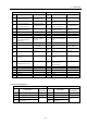
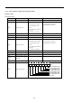
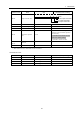
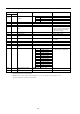
Command Code
Reading Writing
Name Data/Unit Description
C Terminal P1 output Terminal P1 output status
D Terminal P2 output Terminal P2 output status
E Reserved —
110h
(Cont’d)
—
Inverter status
(Cont’d)
bit
F Reserved —
111h — Reserved — —
112h — Torque monitor
*2
-300.0% to +300.0% Sets the current motor torque.
113h — Reserved — —
114h — Operation frequency set
value
0.0Hz to 400.0Hz When the PLC does not have the
frequency reference right set to the
inverter, the value is determined
by the inverter setting.
115h — Output frequency 0.0Hz to 400.0Hz Current output frequency
116h — Output current 0.1A Current output current
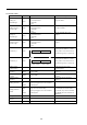
117h — INV terminal A1 analog
input
0.1% —
118h — Main circuit DC voltage 0.1V Sets the value of the main circuit
DC voltage.
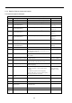
119h — Error Alarm 1 Refer to the following table. —
11Ah — Error Alarm 2 Refer to the following table. —
11Bh — Error Alarm 3 Refer to the following table. —
11Ch — INV terminal A3 analog
input
—
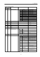
0 Terminal S1 input
1 Terminal S2 input
2 Terminal S3 input
3 Terminal S4 input
4 Terminal S5 input
5 Terminal S6 input
6 Terminal S7 input
7 Terminal S8 input
8 Terminal S9 input
*1
9 Terminal S10 input
*1
A Terminal S11 input
*1
B Terminal S12 input
*1
11Dh — INV sequence input bit
C to F Not used
The input status of terminals S1 to
S11 (bits 0 to B) is in HEX data.
11Eh — INV terminal A1 analog
input
-1540 to 1540 / -11V to +11V —
11Fh — PG counter 2 1 —
*1 Applicable only for G7-series Inverters.
*2 Enabled when A1-02 (control mode selection) is set to "3" for flux vector control, "2" for
open-loop control or "3" for flux vector control.