
User`s manual


5-6
5
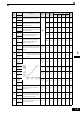
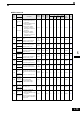
* 1. The setting ranges for acceleration/deceleration times depends on the setting of C1-10 (Acceleration/deceleration Time Setting Unit). If C1-10 is set to
0, the setting range is 0.00 to 600.00 (s).
* 2. The given setting range is valid if Heavy Duty is selected (C6-01=0, default setting). If Normal Duty 1 or 2 is selected (C6-01=1 or 2) the setting range
will be 0.0 to 400.0 Hz.
* 3. These are values for a 200 V class Inverter. Values for a 400 V class Inverter are double.
* 4. The factory setting will change when the control method is changed. (Open Loop Vector control factory settings are given.)
* 5. After autotuning, E1-13 will contain the same value as E1-05.
* 6. The factory setting depends on the Inverter capacity. (The value for a 200 V Class Inverter for 0.4 kW is given.)
* 7. The setting range is from 10% to 200% of the Inverter rated output current. (The value for a 200 V Class Inverter for 0.4 kW is given.)
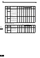
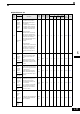
F1-01
PG constant
Sets the number of PG pulses (pulse
generator or encoder).
0 to
60000
1024 No No Q No Q 380H
PG Pulses/
Rev
H4-02
Gain (termi-
nal FM)
Sets the multi-function analog output 1
(terminal FM) gain.
Sets the percentage of the monitor item
that is equal to 10V/20mA output at ter-
minal FM. Note that the maximum out-
put voltage/current is 10V/20mA.
0 to
1000%
100%YesQQQQ41EH
Terminal
FM Gain
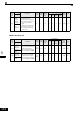
H4-05
Gain (termi-
nal AM)
Sets the multi-function analog output 2
(terminal AM) gain.
Sets the percentage of the monitor item
that is equal to 10V/20mA output at ter-
minal AM. Note that the maximum out-
put voltage/current is 10V/20mA.
0 to
1000%
50%YesQQQQ421H
Terminal
AM Gain
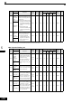
L1-01
Motor pro-
tection
selection
Set to enable or disable the motor over-
load protection function using the elec-
tronic thermal relay.
0: Disabled
1: Protection for general purpose motor
(fan cooled)
2: Protection for frequency converter
motor (external cooled)
3: Protection for special vector control
motor
When the inverter power supply is
turned off, the thermal value is reset, so
even if this parameter is set to 1, protec-
tion may not be effective.
When several motors are connected to
one Inverter, set to 0 and ensure that
each motor is equipped with a protection
device.
0 to 31 NoQQQQ480H
MOL Select
L3-04
Stall preven-
tion selec-
tion during
deceleration
0: Disabled (Deceleration as set. If
deceleration time is too short, a main
circuit overvoltage may result.)
1: Enabled (Deceleration is stopped
when the DC bus voltage exceeds
the stall prevention level.
Deceleration restarts when voltage
falls below the stall level again.)
2: Intelligent deceleration mode
(Deceleration rate is automatically
adjusted so that in Inverter can
decelerate in the shortest possible
time. The set deceleration time is
disregarded.)
3: Enabled (with Braking Resistor Unit)
When a braking option (Braking Resis-
tor, Braking Resistor Unit, Braking
Unit) is used, always set to 0 or 3.
0 to 31 NoQQQQ492H
StallP Decel
Sel
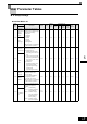
Param-
eter
Num-
ber
Name
Description
Setting
Range
Factory
Setting
Change
during
Opera-
tion
Control Methods
MEMO
BUS
Regis-
ter
V/f
V/f
with
PG
Open
Loop
Vector
Closed
Loop
Vector
Display