
User`s manual


5-60
5
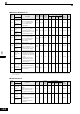
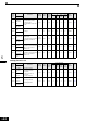
Digital Operator Parameters: o
Monitor Selections: o1
Param-
eter
Num-
ber
Name
Description
Setting
Range
Factory
Setting
Change
during
Opera-
tion
Control Methods
MEMO-
BUS
Register
Page
V/f
V/f
with
PG
Open
Loop
Vector
Closed
Loop
Vector
Display
o1-01
Monitor
selection
Set the number of the 4rd.
monitor item to be displayed
in the Drive Mode. (U1-)
(On LED operator only.)
4 to 33 6 Yes A A A A 500H 6-130
User Moni-
tor Sel
o1-02
Monitor
selection
after power
up
Sets the monitor item to be
displayed when the power is
turned on.
1: Frequency reference
2: Output frequency
3: Output current
4: The monitor item set for
o1-01
1 to 4 1 Yes A A A A 501H 6-130
Power-On
Monitor
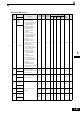
o1-03
Frequency
units of ref-
erence set-
ting and
monitor
Sets the units that will be set
and displayed for the fre-
quency reference and fre-
quency monitor.
0: 0.01 Hz units
1: 0.01% units
(Maximum output
frequency is 100%)
2 to 39: rpm units (Set the
motor poles.)
40 to 39999: User
desired display Set
the desired values for
setting and display
for the max. output
frequency.
Example: When the max. out-
put frequency value is 200.0,
set 12000
0 to
39999
0 No A A A A 502H 6-131
Display
Scaling
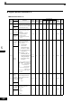
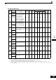
o1-04
Setting unit
for fre-
quency
parameters
related to V/
f characteris-
tics
Set the setting unit for fre-
quency reference-related
parameters.
0: Hz
1: min
−1
0 or 1 0 No No No No A 503H 6-131
V/f Display
Unit
o1-05
LCD Dis-
play contrast
adjustment
Sets the contrast on the
optional LCD operator
(JVOP-160).
1: light
2:
3: normal
4:
5: dark
0 to 5 3 Yes A A A A 504H 6-131
LCD Con-
trast
Sets the value that is
to be displayed at
100% excluding the
decimal point.
Sets the number of
decimal places.