
User`s manual


5-70
5
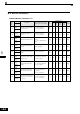
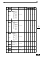
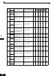
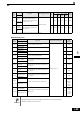
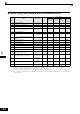
Factory Settings that Change with the Control Method (A1-02)
* 1. The settings are 0.05 (Closed Loop Vector) / 2.00 (Open Loop vector) for inverters of 55kW or larger.
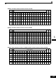
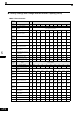
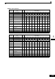
* 2. Settings vary as shown in the following tables depending on the Inverter capacity and E1-03.
* 3. The settings shown are for 200 V class Inverters. The values will double for 400 V class Inverters.
* 4. The given setting range is valid if Heavy Duty is selected (C6-01=0, default setting). If Normal Duty 1 or 2 is selected (C6-01=1 or 2) the setting range
will be 0.0 to 400.0 Hz.
Param
eter
Num-
ber
Name Setting Range Unit
Factory Setting
V/f Control
A1-02=0
V/F with
PG
A1-02=1
Open Loop
Vector
A1-02=2
Closed
Loop Vec-
tor
A1-02=3
b3-01 Speed search selection 0 to 3 - 2 3 2 -
b3-02 Speed search operating current 0 to 200 1% 120 - 100 -
b8-02 Energy saving gain 0.0 to 10.0 - - - 0.7 1.0
b8-03 Energy saving filter time constant 0.0 to 10.0 - - -
0.50
*1
0.01
*1
C3-01 Slip compensation gain 0.0 to 2.5 - 0.0 - 1.0 1.0
C3-02
Slip compensation primary delay time con-
stant
0 to 10000 1 ms 2000 - 200 -
C4-02
Torque compensation primary delay time
constant
0 to 10000 1 ms 200 200 20 -
C5-01 ASR proportional gain 1 0.00 to 300.00 - - 0.20 - 20.00
C5-02 ASR integral time 1 0.000 to 10.000 1 ms - 0.200 - 0.500
C5-03 ASR proportional gain 2 0.00 to 300.00 - - 0.02 - 20.00
C5-04 ASR integral time 2 0.000 to 10.000 1 ms - 0.050 - 0.500
C5-06 ASR delay time 0.000 to 0.500 0.001 - - - 000.4
d5-02 Torque reference delay time 0 to 1000 1 ms - - - 0
E1-07
E3-05
Mid. output frequency (VB)
*2
0.0 to 150.0
*4
0.1 V 2.5 2.5 3.0 -
E1-08
E3-06
Mid. output frequency voltage (VB)
*2
0.0 to 255.0
(0.0 to 510.0)
0.1 V
15.0
*2*3
15.0
*2*3
13.2 -
E1-09
E3-07
Min. output frequency (FMIN)
0.0 to 150.0
*4
0.1 Hz
1.2
*2
1.5
*2
0.5 0.0
E1-10
E3-08
Min. output frequency voltage (VMIN)
*2
0.0 to 255.0
(0.0 to 510.0)
0.1 V
9.0
*2*3
9.0
*2*3
2.4 -
F1-09 Over speed detection time 0.0 to 2.0 1 - 1.0 - 0.0