
User`s manual


6-8
6
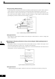
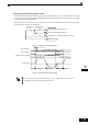
2-Step Switching: Master/Auxiliary
If performing 2-step switching between master and auxiliary speed frequencies, input the master speed fre-
quency reference to control circuit terminal A1, and input the auxiliary speed frequency reference to A2.
When terminal S3 (multi-step speed command 1) is OFF, terminal A1 input (master speed frequency refer-
ence) will be the Inverter frequency reference, and when terminal S3 is ON, terminal A2 input (auxiliary
speed frequency reference) will be the Inverter frequency reference.
Fig 6.7 Master/Auxiliary Frequency Reference Input
Setting Precautions
When inputting a voltage signal to terminal A2, turn OFF pin 2 on DIP switch S1 to switch to voltage input
(factory setting is ON).
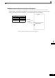
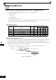
Inputting the Frequency Reference Using a Current Signal / Making Analog Input A1
Multifunctional
The frequency reference can be input from control circuit terminal A2 using a 4-20mA current signal. To use
this function parameter H3-13 must be set to 1 (terminal A1/A2 switching).
In this case A2 becomes the master frequency input and A1 becomes multi-functional. The function for the
analog input A1 can be set in parameter H3-09.
Fig 6.8 Frequency Reference Using Current
Setting Precautions
• When inputting a current signal to terminal A2, turn ON pin 2 on DIP switch S1 (factory setting: ON).
0 to 10 V input
Inverter
+V (Power supply: 15 V,
20 mA)
A1(Master frequency
reference)
DIP switch S1
SN Digital input neutral
S3 Multi-step speed
command 1
Master/
Auxiliary
A2(Auxiliary frequency
reference)
AC (Analog common)
2 kΩ
2 kΩ
2 kΩ
0 to 10 V
input
Inverter
+V (Power supply: 15 V,
A1(Auxiliary frequency
A2(Master frequency
AC (Analog common)
4 to 20 mA
DIP switch S1