
User`s manual


6-26
6
Adjusting Frequency References
Adjusting Analog Frequency References
The analog reference values can be adjusted using the gain and bias functions for the analog inputs.
Related Parameters
Adjusting Analog Frequency Reference Using Parameters
The frequency reference can be input from the control circuit terminals using analog voltage or current signals
(analog input A2 only).
The input signal levels can be selected using
• H3-01 for the analog input A1
• H3-08 for the analog input A2
Adjustments to the signals can be made using:
• H3-02 (Gain) and H3-03 (Bias) if analog input A1 is selected to be the frequency reference input
• H3-10 (Gain) and H3-11 (Bias) if analog input A2 is selected to be the frequency reference input
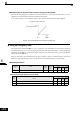
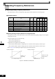
Refer to Fig 6.29 for adjusting the signal using the gain and bias functions.
Fig 6.29 Terminals A1 and A2 Inputs
Parameter
No.
Name
Factory
Setting
Change
during
Opera-
tion
Control Methods
V/f
V/f with
PG
Open
Loop
Vector
Closed
Loop
Vector
H3-01Multi-function analog input terminal A1 signal level selection0 No AAAA
H3-02 Frequency reference terminal A1 input gain 100.0% Yes AAAA
H3-03Frequency reference terminal A1 input bias 0.0%YesAAAA
H3-08Multi-function analog A2 signal level selection 2 No AAAA
H3-09Multi-function analog A2 function selection 0 No AAAA
H3-10 Multi-function analog A2 input gain 100.0% Yes AAAA
H3-11 Multi-function analog A2 input bias 0.0% Yes AAAA
H3-12 Analog input filter time constant 0.03 s No AAAA
H3-13Terminal A1/A2 switching 0 No AAAA
Frequency reference
Terminal A1 input
Terminal A1
input voltage
Frequency reference
Terminal A2 input
Terminal A2 input
voltage (current)