
User`s manual


6-27
6
Adjusting Frequency Gain Using an Analog Input
When H3-09 is set to 1 (frequency gain), the frequency gain can be adjusted using analog input A2.
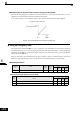
Fig 6.30 Frequency Gain Adjustment (Terminal A2 Input)
The frequency gain for terminal A1 is the product of H3-02 and gain which is input at terminal A2. For exam-
ple, when H3-02 is set to 100% and the terminal A2 input is 5 V, the frequency reference gain will be 50%.
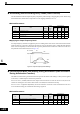
Fig 6.31 Frequency Gain Setting Example
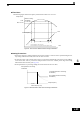
Adjusting Frequency Bias Using an Analog Input
When parameter H3-09 is set to 0 (Frequency Bias), the frequency equivalent to the terminal A2 input voltage
is added to A1 as a bias.
Fig 6.32 Frequency Bias Adjustment (Terminal A2 Input)
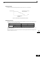
For example, if H3-02 is 100%, H3-03 is 0%, and the terminal A2 input is 1 V, the frequency reference when
0 V is input to A1 will be 10% of the maximum output frequency (E1-04).
Fig 6.33 Frequency Bias Setting Example
Frequency gain
Multi-function analog input
terminal A2 input level
0 10 V
100 %
50 %
H3-02
H3-02 x 0.5
Frequency reference
terminal A1 input voltage
Frequency bias
Multi-function analog input
terminal A2 input level
10 %
Bias
0 V 10 V
H3-02
Frequency reference
Terminal A1 input voltage