
User`s manual


6-73
6
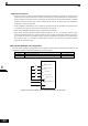
Stopping the Inverter on External Device Errors (External Error Function)
The external error function activates the error contact output and stops the Inverter operation. Using this func-
tion the inverter operation can be stopped on peripheral devices break down or other errors. The digital opera-
tor will display EFx (External error [input terminal Sx]). The x in EFx shows the number of the terminal at
which the external error signal is input. For example, if an external error signal is input to terminal S3, EF3
will be displayed.
To use the external error function, set one of the values 20 to 2F in one of the parameters H1-01 to H1-05 (dig-
ital input terminal S3 to S7 function selection).
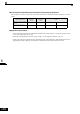
Select the value to be set in H1-01 to H1-05 from a combination of any of the following three conditions.
• Signal input level from peripheral devices
• External error detection method
• Operation after external error detection
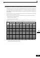
The following table shows the relationship between the combinations of conditions and the set value in H1-
.
* 1. Sets the input level at which errors are detected. (NO contact: External error when ON; NC contact: External error when OFF).
* 2. Set the detection method to detect errors using either constant detection or detection during operation.
Constant detection: Detects while power is supplied to the Inverter.
Detection during operation: Detects only during Inverter operation.
Set
Value
Input Level
(See Note *1)
Error Detection Method (See
Note *2)
Operation During Error Detection
NO Contact NC Contact
Constant
Detection
Detection
During
Operation
Decelerate to
Stop (Error)
Coast to Stop
(Error)
Emergency
Stop (Error)
Continue
Operation
(Warning)
20 Yes Yes Yes
21 Yes Yes Yes
22 Yes Yes Yes
23 Yes Yes Yes
24 Yes Yes Yes
25 Yes Yes Yes
26 Yes Yes Yes
27 Yes Yes Yes
28 Yes Yes Yes
29 Yes Yes Yes
2A Yes Yes Yes
2B Yes Yes Yes
2C Yes Yes Yes
2D Yes Yes Yes
2E Yes Yes Yes
2F Yes Yes Yes