
User`s manual


6-110
6
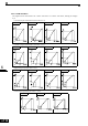
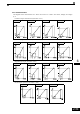
Setting the V/f Pattern 1
Using the E1- parameters the Inverter input voltage and the V/f pattern can be set as needed. It is not rec-
ommended to change the settings when the motor is used in Open Loop or Closed Loop vector control mode.
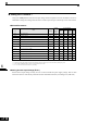
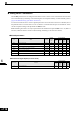
Related Parameters
* 1. These are values for a 200 V Class Inverter. Values for a 400 V Class Inverter are double.
* 2. The factory setting will change when the control method is changed. (Open Loop Vector control factory settings are given.)
* 3. The contents of parameters E1-11 and E1-12 are ignored when set to 0.00.
* 4. E1-13 is set to the same value as E1-05 by autotuning.
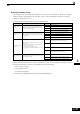
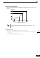
Setting Inverter Input Voltage (E1-01)
Set the Inverter input voltage correctly in E1-01 so that it matches the power supply voltage. This set value
will be the reference value for the protection functions and similar functions (overvoltage level, stall level).
Parameter
No.
Name
Factory
Setting
Change
during
Opera-
tion
Control Methods
V/f
V/f with
PG
Open
Loop
Vector
Closed
Loop
Vector
E1-01 Input voltage setting
200 V
*1
No QQQQ
E1-03 V/f pattern selection F No Q Q No No
E1-04 Max. output frequency (FMAX) 50.0 Hz No QQQQ
E1-05 Max. voltage (VMAX)
200.0 V
*1
No QQQQ
E1-06 Base frequency (FA) 50.0 Hz No QQQQ
E1-07 Mid. output frequency (FB)
3.0 Hz
*2
No A A A No
E1-08 Mid. output frequency voltage (VB)
13.2 V
*1*2
No A A A No
E1-09 Min. output frequency (FMIN)
0.5 Hz
*2
No QQQA
E1-10 Min. output frequency voltage (VMIN)
2.4 V
*1*2
No A A A No
E1-11 Mid. output frequency 2
0.0 Hz
*3
No AAAA
E1-12 Mid. output frequency voltage 2
0.0 V
*3
No AAAA
E1-13 Base voltage (VBASE)
0.0 V
*4
No AAQQ