
User`s manual


2-18
2
Connecting a Braking Resistor Unit (LKEB) and Braking Unit (CDBR)
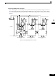
Connect a Braking Resistor Unit and Braking Unit to the Inverter as shown in the Fig 2.8. The internal braking
resistor overheat protection must be disabled (See table below).
The Braking Resistor Unit will not work properly if L3-04 is set to 1 (i.e., if stall prevention is enabled for
deceleration). Hence the deceleration time may be longer than the set time (C1-02/04/06/08).
To prevent the braking unit/braking resistor from overheating, design the control circuit to turn OFF the power
supply using the thermal overload relay contacts of the units as shown in Fig 2.8.
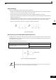
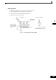
200 V and 400 V Class Inverters with 0.4 to 18.5 kW Output Capacity
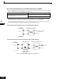
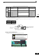
200 V and 400 V Class Inverters with 22 kW or higher Output Capacity
Fig 2.8 Connecting the Braking Resistor and Braking Unit
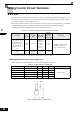
L8-01 (Protection selection for internal DB resistor) 0 (Disable overheat protection)
L3-04 (Stall prevention selection during deceleration)
(Select either of them.)
0 (Disable stall prevention function)
3 (Enable stall prevention function with braking resistor)
Inverter
Braking Resistor Unit (LKEB)
Thermal overload
relay contact
Inverter
Braking Resistor Unit (LKEB)
Thermal overload
relay contact
CDBR Braking Unit
Thermal overload re-
lay contact