
User`s manual


2-28
2
Installing and Wiring Option Cards
Option Card Models and Specifications
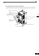
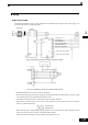
Up to two Option Cards can be mounted in the Inverter. You can mount one card into each of the two places
on the controller card (A, and C) like shown in Fig 2.15.
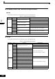
Table 2.12 lists the type of Option Cards and their specifications.
Installation
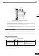
Before mounting an Option Card, remove the terminal cover and be sure that the charge indicator inside the
Inverter does not glow anymore. After that remove the Digital Operator and front cover and then mount the
Option Card.
Refer to documentation provided with the Option Card for the mounting instructions for option slots A and C.
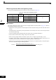
Table 2.12 Option Cards
Card Model Specifications
Mounting
Location
PG Speed Control Cards
PG-B2
Two phase (phase A and B), +12V inputs, max.
response frequency: 50 kHz
A
PG-X2
Three phase (phase A, B, Z), line driver inputs
(RS422), max. response frequency: 300 kHz
A
DeviceNet
communications card
SI-N1/
PDRT2
Option card for DeviceNet fieldbus C
Profibus-DP
communications card
SI-P1 Option card for Profibus-DP fieldbus C
InterBus-S
communications card
SI-R1 Option card for InterBus-S fieldbus C
CANOpen
communications card
SI-S1 Option card for CANOpen fieldbus C
Analog Input Cards
AI-14U
2 channel high resolution analog input card
Channel 1: 0 to 10 V (20 kΩ)
Channel 2: 4 to 20 mA (250 Ω)
Resolution: 14 Bit
C
AI-14B
3 Channel high resolution analog input card
Signal level: -10 to +10 V (20 kΩ)
4 to 20 mA (250 Ω)
Resolution: 13 Bit + sign
C
Digital Input Cards
DI-08 8 bit digital speed reference input card C
DI-16H2 16 bit digital speed reference input card C