Operators manual Models: ZHDD61271 ZHDD72341 Please read these instructions carefully and make sure you understand them before using the machine. MANUAL NO. 110891REV.
©2005Yazoo/Kees Power Equipment. All righs reserved. Beatrice, NE Printed U.S.A.
INDEX Contents ....................................................... 3 Introduction .................................................. 4 Congratulations .......................................... 4 General ...................................................... 4 Driving and Transport on Public Roads ..... 4 Operating ................................................... 4 Good Service ............................................. 5 Manufacturing Number............................... 5 Symbols and Decals ...
INTRODUCTION Introduction Congratulations Thank you for purchasing a Yazoo/Kees ride-on mower. This machine is built for the greatest efficiency and rapid mowing of large areas. Conveniant controls and a hydrostatic transmission regulated by steering levers also contribute to the machine’s performance. This manual is a valuable document. Following the instructions (use, service, maintenance, etc.) can considerably increase the lifespan of your machine and even increase its resale value.
INTRODUCTION Good Service Yazoo/Kees’s products are sold only in specialized retail stores with complete service. This ensures that you as a customer receive only the best support and service. Before the product is delivered, the machine has, for example, been inspected and adjusted by your retailer, see the certificate in the Service Journal in this operator’s manual. When you need spare parts or support in service questions, warranty issues, etc.
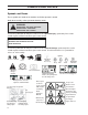
SYMBOLS AND DECALS Symbols and Decals These symbols are found on the machine and in the operator’s manual. Study them carefully so that you know what they mean. WARNING! Xxxxxxxxxx xxx xxxxx xxxxxxxx. Xxxxxx xxxxx xxxxxxxxx xxxxx xxxxx xxx x xxxxx. Used in this publication to notify the reader of a risk of personal injury, particularly if the reader should neglect to follow instructions given in the manual. IMPOR TANT INFORMA TION Xxxxxxx xxxx xxxxxxxx xxx xxx xxxx xxxxxx xx.
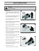
SAFETY INSTRUCTIONS Safety Instructions These instructions are for your safety. Read them carefully. WARNING! This symbol means that important safety instructions need to be emphasized. It concerns your safety. General Use • Read all instructions in this operator’s manual and on the machine before starting it. Ensure that you understand them and then abide by them. • Learn how to use the machine and its controls safely and learn how to stop quickly. Also learn to recognize the safety decals.
SAFETY INSTRUCTIONS • Be careful when rounding fixed objects, so that the blades do not hit them. Never drive over foreign objects. • Only use the machine in daylight or in other well-lit conditions. Keep the machine a safe distance from holes or other irregularities in the ground. Pay attention to other possible risks. • Never use the machine if you are tired, if you have consumed alcohol, or if you are taking other drugs or medication that can affect your vision, judgement, or coordination.
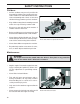
SAFETY INSTRUCTIONS Driving on Slopes Driving on slopes is one of the operations where the risk is greatest that the driver will lose control or the machine will tip over, which can result in serious injury or death. All slopes require extra caution. If you cannot reverse up a slope or if feel unsure, do not mow the slope. Do as follows: • Remove obstacles such as stones, tree branches, etc. • • Mow up and down, not side-to-side. Never drive the rider on terrain that slopes more than 10°.
SAFETY INSTRUCTIONS Children: • Serious accidents may occur if you fail to be on guard for children in the vicinity of the machine. Children are often attracted to the machine and mowing work. Never assume that children will stay put where you last saw them. • Keep children away from the mowing area and under close supervision by another adult. • Keep an eye out and shut off the machine if children enter the work area.
SAFETY INSTRUCTIONS • Allow the engine to cool before refueling. Do not smoke. Do not fill fuel in the vicinity of sparks or open flames. • If leaks arise in the fuel system, the engine must not be started until the problem has been resolved. • Store the machine and fuel in such a way that there is no risk of leaking fuel or fuel vapor leading to damages.
SAFETY INSTRUCTIONS • Never use the machine indoors or in spaces lacking proper ventilation. The exhaust fumes contain carbon monoxide, and odorless, poisonous, and lethal gas. • Stop and inspect the equipment if you run over or into anything. If necessary, make repairs before starting. • Never make adjustments with the engine running. • The machine is tested and approved only with the equipment originally provided or recommended by the manufacturer.
SAFETY INSTRUCTIONS Roll Over Protection System WARNING! This structure’s capability may be imparired by structural damage if overturned, or alteration occurs. If any of these conditions take place, the total structure MUST be replaced. DO NOT use ROPS as a lifting, attaching or anchoring point. DO NOT exceed Max GVW: 3553; ROPS mass 72 lbs./32 kg. Read machine operator’s manual before each use. Securely fasten your seat belt if the unit has a ROPS.
SETUP AND ADJUSTMENTS WARNING! No settings or adjustments are to be made unless: Engine is stopped, key has been removed, park brake is on and battery cable removed from battery. Setup Uncrate machine. Seat Assembly 1. Remove inner seat latch pin `E’ ring and slide pin out to left releasing latch, spring and washer. 2. Rotate latch so hook will be down and pointed forward, as shown, when seat is in upright position. Short legs on latch will be under seat mounting frame. 3.
SETUP AND ADJUSTMENTS ROPS Assembly (Roll Over Protection System) ROPS Assembly Components 1 - Top Loop 1 - Left Side Post 1 - Right Side Post 1 - Hardware Bag 2 - 1/2” Latch Pins w/lanyard 2 - 1/2C x 3 1/4” Cap screws 2 - 1/2C Centerlock nuts 4 - 5/8C X 3” Cap screws 4 - 5/8C Centerlock nuts 8 - 5/8 Washer, flat 2 - Knobs (all hardware Grade 5). 1. Remove roll bar and parts bag from the box. 2. Install roll bar side posts. a. Locate the LEFT and RIGHT side posts. b.
SETUP AND ADJUSTMENTS Control Arms Remove top bolt in control arm and loosen bottom bolt, rotate the control levers to the upright position. Align the levers so they are even in the neutral position. Reinstall hardware and tighten. FIG - 1 Wire Harness 1. Connect the wire harness from the seat to the frame harness. Control Arm Motion Control Lever FIG - 1 Engine Oil Check engine oil with dip stick. Add if needed per the engine manufactures specifications.
SETUP AND ADJUSTMENTS Mower Deck Leveling Position machine on a flat surface. Preferably level concrete. Loosen the nuts (A & B) directly behind each ball joint on both rods (C) that connect the pump arm to the motion control assemblies. FIG - 5 Check the tire pressure in all four tires. Inflation should be 15 psi. Start the engine. The park brake must be engaged and the motion control levers in the neutral slots to start the engine.
CONTROLS Presentation This operator’s manual describes the Yazoo/ Kees Lever-Steered Rider Mower. The mower is fitted with a liquid cooled, 3 cylinder Daihatsu diesel engine (27 HP) or Daihatsu Turbo diesel engine (34 HP). Transmission from the engine is made via two belt-driven hydraulic pumps, which in turn drive a hydraulic motor for each drive wheel. Using the left and right steering controls, the flow is regulated and thereby the direction and speed.
CONTROLS Gauges Water temperature gauge- indicates coolant temperature and warns of overheat situation. Ammeter - indicates amount of electrical flow at the battery. Under normal operating conditions the needle will be slightly on the plus (+) side of the gauge, showing that current is being supplied to the battery. At idle speed, the indicator may be at zero or on the negative (-) side.
CONTROLS Engaging the Mower Deck In order to engage the mower deck, pull the knob out; the mower deck is disengaged when the knob is depressed. Deck should be engaged at mid throttle and disengaged at idle speed to prolong clutch life. Engaging the mower deck BAM-2 Parking Brake The parking brake is found on the left of the machine. Pull the lever back to activate the brake and push forward to release it.
CONTROLS Motion Control Levers The machine’s speed and direction are continuously variable using the two motion control levers. The motion control levers can be moved forward or backward from a neutral position. Furthermore, there is a neutral position, which is locked if the motion control levers are moved outward into the neutral slots. When both controls are in the neutral position (N), the machine stands still. The motion control levers on each side of the mower control the direction of movement.
CONTROLS If the steering controls are in uneven positions when standing still, they can be adjusted using the adjustment screws, not the link system, for the controls ADJUSTIN GSCREWS Adjusting screws Hydraulic Lift Switch Used to raise and lower the mower deck hydraulically. Only used on units with power deck lifts. Push switch forward to lower the deck and pull backward to raise the deck.
CONTROLS Refueling The machine has two fuel tanks, one on each side just behind the seat. The tanks hold 11.4 gallons, 5.7 gallons each. The engine is run on clean, fresh, diesel fuel with a minumum of 40 cetane. WARNING! Diesel fuel is highly flammable. Observe caution and fill the tanks outdoors (see the safety rules). BAM-8 Fuel tanks Fuel Shut-Off The fuel shut-off is placed to the right side of the seat. The shut-off has three positions; right tank, left tank and off position.
CONTROLS Manual Lifting Lever with Foot Assist for the Mower Deck The lifting lever is used to place the mower deck in the transport position or one of the 17 different cutting height positions. The cutting height is set by placing a pin in the hole for the desired cutting height and the pin is then locked on the inside (hidden in the illustration) with the supplied cotter pin. 1. Pull the lever backward while pushing on the foot pedal, lifting the deck to the locked position. The deck is then raised. 2.
CONTROLS Relays The relays and glow plug timer are located in a holder to the right side of the seat. GLOW PLUG TIMER GLOW PLUG RELAY START RELAY SEAT RELAY RUN RELAY Relays BAM-12 Tracking The tracking knob is located in front of the left control lever. Rotating this knob allows fine tuning adjustments so that the machine tracks straight with the drive levers in the full forward position.
OPERATION Running Before Starting • Read the sections Safety Instructions and Presentation before starting the machine. • Perform the daily maintenance before starting (see Maintenance Schedule in the Maintenance section). • Check that there is sufficient fuel in the fuel tanks. • Adjust the seat to the desired position.
OPERATION 5. Move the steering controls outward to the locked (outer) neutral position. STEERINGPOSITION Steering controls in the outward, locked neutral position 6. Move the throttle to the middle position.
OPERATION 7. Open the fuel switch for the selected fuel tank. BAM-9 Open the fuel switch 8. Turn the ignition key to the run position to activate the glow plug. Wait till the light goes out, then turn key to start position. GLOW PLUG INDICATOR STOP IMPORTANT INFORMATION Wait till the glow plug light goes out or damage could result to the engine. CONSOLE2 9. When the engine starts, immediately release the ignition key back to the run position.
OPERATION 10. Set the desired engine speed with the throttle. Allow the engine to run at a moderate speed, “half throttle”, for 1 minute before increasing the engine speed. Use full throttle when mowing. WARNING! Never run the engine indoors, in enclosed or poorly ventilated spaces. Engine exhaust fumes contain poisonous carbon monoxide. BAM - 2 Set the engine speed Running 1. Release the parking brake by moving the lever forward. Released parking brake 2.
OPERATION 3. Select the cutting height by placing the pin in one of the holes. Lock the pin on the inside with the cotter pin. 4. Press in the stop handle, counter hold, and carefully move the lifting lever forward from the transport position toward the pin on manual units. 5. On power units push the hydraulic lift switch forward to lower the deck to the selected pin position. IMPORTANT INFORMATION The mower deck’s anti-scalp rollers should be evenly adjusted. See Maintenance section.
OPERATION disengaged before the motion control levers can be moved from the neutral slots or the engine will kill. By moving the levers an equal amount forward or back the machine will move in a straight line in that direction. Movement of either lever forward will cause the right or left wheel to rotate in a forward direction. To stop movement pull both levers into the neutral position.
OPERATION dense, the driving speed can be increased without noticeably depreciating the mowing result. • The finest lawns are obtained by mowing often. The mowing becomes more even and the grass clippings more evenly distributed over the mown area. The total time taken is not increased as a higher driving speed can be used without poorer mowing results. • Avoid mowing wet lawns.
OPERATION Stopping the Engine Allow the engine to idle a minute in order to attain normal operating temperature before stopping it if it has been worked hard. Avoid idling the engine for long periods. 1. Disengage the mower deck by depressing the control. 2. On manual decks raise the mower deck by pulling the lifting lever backward to the transport position. BAM - 2 Disengaging the mower deck 3. On power decks raise the deck by pulling back the hydraulic switch on the console. 4.
MAINTENANCE Maintenance Maintenance Schedule The following is a list of maintenance procedures that must be performed on the machine. For those points not described in this manual, visit an authorized service workshop. An annual service carried out by an authorized service workshop is recommended in order to maintain your machine in the best possible condition and to ensure safe operation.
MAINTENANCE Daily maintenance Maintenance Before After Maintenance interval At Weekly in hours least mainteonce nance each 25 50 100 150 300 year Lubricate the steering control shafts * * * Lubricate the mower deck’s struts Lubricate the mower deck’s cutting height adjuster Check/adjust the cutting height * Change inner (safety) air filter element * Clean the air cleaner’s filter cartridge 2) (paper filter) * Change the engine oil 1) * * * Change the hydraulic oil filter (every 300 hours) Repl
MAINTENANCE Checking the Safety System The machine is equipped with a safety system that prevents starting or driving under the following conditions. The engine can only be started when: 1. The mower deck is disengaged. 2. The motion control levers are in the outer, locked neutral position. 3. The driver is sitting in the driver’s seat. 4. The parking brake is on. Make daily inspections to ensure that the safety system works by attempting to start the engine when one of the conditions is not met.
MAINTENANCE Checking the Engine’s Cooling Air Intake Check that the engine’s cooling air intake is free from leaves, grass, and dirt. If the cooling air intake is clogged, engine cooling deteriorates, which can lead to engine damage. The radiator screen can be removed and cleaned . Checking and Adjusting the Throttle Cable Check that the engine responds to throttle Check and clean the cooling air intake increases and that a proper engine speed is attained at full throttle.
MAINTENANCE Replacing the Air Filter If the engine seems weak or runs unevenly and the dust load indicator has turned red the air filter may be clogged. If run with a clogged air filter, disruption of operation can occur. CLAMP Cleaning/replacing the air filter is carried out as follows Only do so when the dust indicator is red. DUST LOAD INDICATOR CLAMP WARNING! Allow the exhaust system to cool before performing service. Risk for burns. 1.
MAINTENANCE Replacing the Fuel Filter The fuel filter is located with the priming pump. Replace the fuel filter every 800 hours (once per season) or more regularly if it becomes clogged. PRIMING PUMP Replace the filter as follows: Unscrew fuel filter from pump and replace. Every 50 hours check for water in the fuel filter. Empty if necessary. Refer to the engine manual. FUEL FILTER Checking Tire Pressures All four tires shall have a pressure of 16 PSI.
MAINTENANCE When refilling the system, it is important that all trapped air be purged. The following procedure will help to insure this: 1. Make sure the engine is level. Fill the overflow reservoir up to the MAX mark with coolant mixture. 2. Slowly fill the radiator to the bottom of the filler neck with coolant mixture. 3. With radiator cap off, start the engine and let it warm up (no-load). Then, if necessary, add more coolant mixture to bring the level back up to the bottom of the filler neck. 4.
MAINTENANCE contact between brake shoes and drum can be felt. Hold in this position. 4. Rotate clevis until clevis pin can just be inserted thru clevis and brake lever with pin resting against rear of the hole in brake lever. 5. Remove clevis pin and rotate clevis two (2) full turns toward rear to allow correct clearance between brake shoes and drum. 6. Temporarily reinstall clevis pin (do not install cotter pin) to keep clevis from turning and tighten jam nut. 7.
MAINTENANCE Checking the Hydraulic System Total System Capacity..................1.125 gal. To check the hydraulic fluid level, locate the hydraulic reservoir under the seat. Remove cap and check level. Fill to 1/4" from top of tank WARNING! If a leak is suspected, use a piece of cardboard or wood, NOT your hands. to check for leaks. Escaping hydraulic oil under pressure can have sufficient force to penetrate the skin, causing serious injury. Ifinjured by escaping fluid, see a doctor at once.
MAINTENANCE Caster Wheels Check every 200 hours. Lift front of unit off of ground so caster wheels can rotate freely. Tighten caster bolt then back off 1/2 turn. Check that wheel rotates freely. If wheel does not rotate freely back the caster bolt off in 1/4 turn increments until wheel rotates freely. NOTE: DO NOT add any type of tire liner or foam fill material to the tires. Excessive loads created by foam filled tires will cause premature failures. Only use O.E.M. specified tires.
MAINTENANCE Begin with either side and put the motion control lever into the neutral position. Adjust the motion control linkage by rotating the double nuts (D) in the proper direction until the wheel stops rotating. See illustration. Move the motion control lever forward then into the neutral position and place it into the neutral slot. The wheel must be stopped completely at this point. Now do the same in reverse and release the lever. The lever should return to neutral on its own.
LUBRICATION Lubrication Lubrication Schedule Lubrication schedule 8011-620 General Remove the ignition key to prevent unintentional movements during lubrication. When lubricating with an oil can, it should be filled with engine oil. When lubricating with grease, unless otherwise stated, a lithium based grease or another chassis or ball bearing grease, offering good corrosion protection should be used. With daily use, the machine should be lubricated twice weekly.
LUBRICATION Lubricating the Cables If possible, grease both ends of the cable and move the controls to end stop positions when lubricating. Refit the rubber covers on the cable after lubrication. Cables with sheaths will bind if they are not lubricated regularly. If a cable binds, it can disrupt operation. If a cable binds, remove the cable and hang it vertically. Lubricate it with thin engine oil until the oil begins to escape from the bottom.
LUBRICATION 3. Engine Oil Changing the Engine Oil Change the engine oil and filter for the first time after 50 hours of operation. Thereafter, the oil should be changed every 150 hours and the filter every other oil change. WARNING! Engine oil can be very hot if it is drained directly after stopping the engine. Allow the engine to cool.
LUBRICATION The oil level should be between the markings on the dipstick. If the level is approaching the “ADD” mark, add the oil to the “FULL” mark on the dipstick. Never fill above the “FULL” mark. The oil is topped off through the dipstick hole. Check your engine manual for the correct type of engine oil for you unit. The dipstick markings The engine holds 3.5 quarts of oil including the filter. 4.
LUBRICATION 5. Front Wheel Mount Lubricate with a grease gun, one zerk for each wheel mount, use 10 pumps of the grease gun at the recommended service intervals. Use only good quality lithium based grease. Grease from well-known brand names (petrochemical companies, etc.) usually maintains a good quality. 6. Front Wheel Bearings Lubricate with a grease gun, one zerk for each set of wheel bearings, 3 to 5 pumps of the grease gun at the recommended service intervals.
LUBRICATION 9. Steering Control Shafts Tip the driver’s seat. Lubricate with a grease gun, one zerk for each steering control shaft, until the grease is forced out. Use only good quality lithium based grease. Grease from well-known brand names (petrochemical companies, etc.) usually maintains a good quality. Lubricating the steering control shafts 8011-578-2 Lubricating struts 8011-577 10. Mower Deck Struts Lubricate with a grease gun, one zerk for each strut, until the grease is forced out.
LUBRICATION 12. Belt Adjuster, Hydraulic Pumps Lubricate using a grease gun, one zerk, until the grease squeezes out. Use only good quality lithium based grease. Grease from well-known brand names (petrochemical companies, etc.) usually maintains a good quality. IMPORTANT INFORMATION Be careful and remove excess lubricant so that is does not come into contact with belts or belt pulley drive surfaces. Lubricating the belt adjuster BAM-24-2 Changing the oil filter BAM--23 13. Changing the Oil Filter 1.
TROUBLE SHOOTING GUIDE Trouble Shooting Guide Problem Cause The engine will not start. • The control for engaging the mower deck is not depressed. • The steering controls are not locked in the neutral position. • The driver is not sitting in the driver’s seat. • The parking brake is not activated. • The battery is dead. • Contamination in the fuel line. • The fuel supply is closed or the valve for the fuel tanks is in the wrong position. • Clogged fuel filter or fuel line.
TROUBLE SHOOTING GUIDE The engine overheats. • Clogged air intake or cooling fins. • Engine overloaded. • Poor ventilation around engine. • Defective engine speed regulator. • Soot in the combustion chamber. • Too little or no oil in the engine. • Water pump not working. • Coolant system clogged. • Coolant level low. Battery not charging. • Poor contact with battery terminal cable connectors. The machine moves slowly, unevenly, or not at all. • Parking brake on. • Venting valve on pump open.
TROUBLE SHOOTING GUIDE The machine vibrates. • The blades are loose. • The blades are incorrectly balanced. • The engine is loose. • Wheels loose.
STORAGE Storage Winter Storage To ready the machine for storage, follow these steps: At the end of the mowing season, the machine 1. Thoroughly clean the machine, especially should be readied for storage (or if it will not be in under the mower deck. Touch up damage to use for longer than 30 days). Fuel allowed to stand the paint and spray a thin layer of oil on the for long periods of time (30 days or more) can leave underside of the mower deck in order to avoid corrosion. 2.
TECHNICAL DATA Technical Data Measurements, Weights, Etc. Length 95 in. Width (lowered discharge chute) 74 in.(61" deck), 85 in. (72" deck) Width (raised discharge chute) 62 in. (61" deck), 73 in. (72" deck) Height 46.5 in. Weight BZ6127D BZ7234D 1540 lbs. 1620 lbs. Cutting width 61 in. and 72 in. Cutting height Adjustable 1.5" to 6" in 1/4" incriments Air pressure, front and rear 16 psi Tires, front 13" x 6.50 - 6, 4-ply smooth tread Tires, rear 26" x 12.
TECHNICAL DATA Clutch Electric w/intragal stop brake rating torque rating 300 ft./lbs. Noise Emissions and Cutting Width Measured noise level YY dB(A) Guaranteed noise level 105 dB(A) Cutting width 61 in. and 72 in.
SERVICE JOURNAL Service Journal Action Delivery Service 1. Charge the battery. 2. Mount the rear wheels. 3. Adjust the tire pressure of all wheels to 16 PSI. 4. Mount the steering controls in the normal position. 5. Connect the lever to the seat stop. 6. Connect the contact box to the cable for the seat’s safety switch. 7. Mount the arm rests on the seat’s back support. 8. Check that the right amount of oil is in the engine. 9. Check that the right amount of oil is in the hydraulic tank. 10.
SERVICE JOURNAL Action 20. Date, mtr reading, stamp, sign Inform the customer about: The need and advantages of following the service schedule. Delivery service has been carried out. The need and advantages of leaving the machine No remaining notes. for service every 300 hours. Certified: The effects of service and maintaining a service journal on the machine’s resale value. Application areas for Mulch kit. 21. Fill in the sales papers, etc. After the First 50 Hours 1.
SERVICE JOURNAL Action 25-Hour Service 1. Check the hydraulic system’s oil level. 2. Check the tire pressures. 3. Lubricate the belt adjuster, mower deck. 4. Lubricate the belt adjuster, hydraulic pumps. 5. Lubricate the belt adjuster, mule drive.
SERVICE JOURNAL Action Date, mtr reading, stamp, sign 50-Hour Service 1. Perform the 25-hour service. 2. Change oil and oil filter for the first time. See engine manual. 3. Check dust load indicator on air filter.Change filter only if indicator is red. See engine manual. 4. Lubricate the front wheel bearings. 5. Lubricate the steering control shafts. 6. Lubricate the mower deck struts. 7. Lubricate the cutting height adjuster. 8.
SERVICE JOURNAL Action 100-Hour Service 62 1. Perform the 25-hour service. 2. Perform the 50-hour service. 3. Change engine oil at 150 hours. See engine manual. 4. Check fuel pump filter. See engine manual. 5. Check fan belt clearance. See engine manual. 6. Clean the cooling fins on the engine and transmission.
SERVICE JOURNAL Action Date, mtr reading, stamp, sign 300-Hour Service 1. Inspect the machine. Come to agreement with the customer as to which additional work is to be carried out. 2. Perform the 25-hour service. 3. Perform the 50-hour service. 4. Perform the 100-hour service. 5. Check/replace the air cleaner’s safety element.
SERVICE JOURNAL Action At Least Once Each Year 1. Replace the air cleaner’s safety element. 2. Replace the air filter’s paper cartridge. 3. Change the engine oil (150 hours). 4. Replace the engine oil filter (300 hours). 5. Change the oil and filter in the hydraulic system (300 hours). 6. Check/adjust the cutting height. 7. Check/adjust the parking brake (50 hours). 8. Change the fuel filter (100 hours). 9. Clean the cooling fins (100 hours). 10.