Model AMP2440P REMOTE BI-DIRECTIONAL POWER AMPLIFIERS FOR 2.4 GHz User and Installation Manual Version 1.2 Sept 1999 \manuals\AMP2440P-FCC.
IMPORTANT SAFETY INFORMATION Connecting the RF output of a radio modem transmitter to a high gain antenna will result in concentrated signal level near the antenna. The field strength radiated by these antennas, when connected to a transmitting Model 2400 Radio Modem with AMP2440P, may exceed FCC mandated RF exposure limits.
2. AMPLIFIER FEATURES.............................................................................................................................................1 3. SPECIFICATIONS .......................................................................................................................................................2 4. AMPLIFIER KIT..........................................................................................................................................................3 5.
1. Description The AMP2440P is a bi-directional amplifier designed for extending the range of 2.4 GHz wireless LAN cards. The Model AMP2440P amplifier is intended only for use with the YDI Model WL2400-PCM and the WL2400-ISA 2.4 GHz Direct Sequence Spread Spectrum Wireless LAN cards. The units provide transmit power amplification as well as receive signal gain. The amplifier is installed right at the antenna’s feed point, providing maximum effectiveness of transmit power.
3. Specifications General Specifications Operating Range: Operating Mode: Connectors: Indicators: Receiver Low Noise Amplifier (LNA) 2400-2483 MHz Bi-directional, half-duplex. Senses RF carrier from transmitter and automatically switches from receive to transmit mode. N-female Frequency Response: Noise Figure: TX and RX LEDs on both the amplifier Third Order Intercept: and the DC power injector Lightening Protection: Direct DC ground at antenna connector on amp.
IMPORTANT FCC REGULATORY AND SAFETY INFORMATION The AMP2440P and the YDI WLAN 2400 WLAN cards must be professionally installed. Table (1) shows the FCC approved antennas that can be used with and without the YDI AMP2440P. When using the amplifier, only the outdoor antennas listed here can be used. The amplifier cannot be used with the small indoor patch antenna (Model A24FP06). It is the responsibility of the installer to ensure that when used in the United States that the requirements in Section 15.
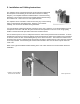
5. Installation and Cabling Instructions The amplifier can be mast mounted using the steel U-bolt included with the unit (Refer to the drawing at the end of the manual for a cabling diagram). The amplifier should be installed with the connectors facing downward. Use an open-end wrench to carefully tighten the bolts using the included nuts. Take care not to over-tighten the bolts. The amplifier can be mounted to a flat surface using any of the mounting holes on the brackets mounting flanges.
6. Amplifier Connections and Indicators Transmit LED: Receive LED: DC Injector Connection: Antenna Connection: This LED glows RED in transmit mode indicating that RF power is applied to the amplifier from the radio. This LED glows GREEN in the receive mode when DC power is applied to the amplifier and is off when transmitting. This “N” Female connector is connected to the DC Power Injector via the transmission cable. This “N” Female connector connects to the antenna with a short length of coax cable.
8. Power Supply The AMP2440P comes with a power supply that have standard 2.1 mm barrel plugs (which are configured as positive (+) tip and negative ( - ) outer conductor). Although normally supplied with a power supply, any regulated 12 Volt DC 1 amp supply can be used. The power supply provided with the kit can be used with 110 or 240 VAC power. 9. Operation The unit operates automatically and there are no user adjustments.
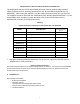
Table A - Conversions from dBm to Watts dBm 0 1 2 3 4 5 6 7 8 9 10 11 12 13 14 15 16 17 18 19 20 21 22 23 24 25 Watts 1.0 mW 1.3 mW 1.6 mW 2.0 mW 2.5 mW 3.2 mW 4.0 mW 5.0 mW 6 mW 8 mW 10 mW 13 mW 16 mW 20 mW 25 mW 32 mW 40 mW 50 mW 63 mW 79 mW 100 mW 126 mW 158 mW 200 mW 250 mW 316 mW dBm 26 27 28 29 30 31 32 33 34 35 36 37 38 39 40 41 42 43 44 45 46 47 48 49 50 Watts 398 mW 500 mW 630 mW 800 mW 1.0 W 1.3 W 1.6 W 2.0 W 2.5 W 3.0 W 4.0 W 5.0 W 6.0 W 8.
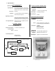
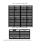
Table C - AMP2440P Typical Installation TYPICAL INSTALLATION DETAILS ANTENNA Omni-directional (shown), or Grid Dish Yagi Antennas (not shown) AMP2440 (mounted to mast with U-Bolt) Drip Loop N-male connector Transmission Line Mast LMR-400, Belden 9913 or other low loss cable to radio room DC P.S. 110/220 VAC Choke RF + DC N-male DC POWER INJECTOR Short length of RG58/U (CAB-RPNM-12“) Model 2400 Radio Modem RS232 cable PC, Router, PLC, etc.