DOC#:01.13.000100 X2 DATA SHEET www.ydlidar.com Shenzhen EAI Technology Co.,Ltd.
CONTENTS 1 PRODUCT OVERVIEW...................................................................... 1 1.1 Product Features ................................................................................ 1 1.2 Applications ........................................................................................ 1 1.3 Installation and Dimensions .............................................................. 1 2 SPECIFICATIONS ............................................................................. 2 2.
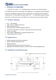
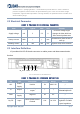
1 PRODUCT OVERVIEW YDLIDAR X2 is a 360° 2D LiDAR(hereinafter referred to as X2) developed by YDLIDAR team. Based on the principle of Triangulation, it is equipped with related optics, electricity, and algorithm design to achieve high-frequency and high-precision distance measurement. The mechanical structure rotates 360 ° to continuously output the angle information as well as the point cloud data of the scanning environment while ranging. 1.
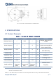
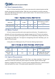
FIG 2 YDLIDAR X2 MECHANICAL DIMENSIONS 2 SPECIFICATIONS 2.1 Product Parameter CHART 1 YDLIDAR X2 PRODUCT PARAMETER Item Min Typical Max Unit Ranging frequency / 3000 / Hz Remarks Ranging 3000 times per second Need to connect to PWM Motor frequency 5 6 8 Hz signal, recommended to use the speed of 6Hz Indoor environment, Ranging distance 0.12 / 8 m Fileld of view / 0-360 / ° / Systematic Error / 2 / cm Range≤1m Statistical Error / 3.
Statistical Error = (Ranging distance - actual distance)/ actual distance * 100%. LiDAR is a precision equipment, which needs to be protected during use. In the use scenarios of high temperature, high and low temperature or strong vibration, the parameter index of relative error will be relatively larger. 2.2 Electrical Parameter CHART 2 YDLIDAR X2 ELECTRICAL PARAMETER Item Min Typical Max Unit Remarks Excessive voltage might Supply voltage 4.8 5 5.
2.4 Data Communication With a 3.3V level serial port (UART), users can connect the external system and the product through the physical interface. After that, you can obtain the real-time scanned point cloud data,device information as well as device status.The communication protocol of parameters are as follows: CHART 4 YDLIDAR X2 SERIAL SPECIFICATION Item Min Typical Max Unit Remarks Baud rate / 115200 / bps High Signal Level 2.4 3.3 3.5 V / Low signal Level 0 0 0.
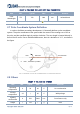
CHART 6 YDLIDAR X2 LASER OPTICAL PARAMETERS Item Laser Wavelength Min Typical Max Unit Remarks 775 793 800 nm Infrared band FDA Class I 2.7 Polar Coordinate System Definition In order to facilitate secondary development, X2 internally defines a polar coordinate system. The polar coordinates of the system take the center of the rotating core of X2 as the pole, and the specified Angle is positive clockwise. The zero Angle is located directly in front of the X2 motor.
3 DEVELOPMENT AND SUPPORT X2 provides a wealth of software interfaces, which can realize the motor enabling control, speed control, range unit enabling control and output control of the system. On this basis, users can also implement the power control and scan control purpose. Also, the 3D model of X2 is disclosed. YDLIDAR provides the graphics debugging Workstation under Windows, as well as the corresponding SDK and ROS development kit to users, which could be downloaded from our website: https://www.
4 REVISE Date Version Content 2018-06-20 1.0 Compose a first draft 2021-07-22 2.