YDLIDAR X4 DEVELOPMENT MANUAL Doc#:01.13.000002 文档编码:01.13.
CONTENTS Working Mechanism ......................................................................................................................... 2 System workflow ........................................................................................................................... 2 System Communication .................................................................................................................... 3 Communication mechanism .......................................................
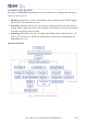
WORKING MECHANISM The system of YDLIDAR X4 (hereinafter referred to as X4) has set 3 working modes: idle mode, scan mode, and stop mode; Idle mode:When X4 is powered on, the default is idle mode. In idle mode, the X4's ranging unit does not work and the laser is not lit. Scan mode:When the X4 enters the scan mode, the ranging unit turns on the laser and starts working. Lidar continuously performs laser sampling on the external environment and outputs it in real time after background processing.
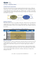
SYSTEM COMMUNICATION Communication mechanism X4 interacts with external devices through commands and data through the serial port. When the external device sends a system command to X4, X4 will parse the system command and return the corresponding reply message. And according to the command content, to switch the corresponding working status. The external system will parse the message according to the content of the message and obtain the response data.
Single reply and continuous reply messages use the same data protocol. The contents of the protocol are: start, response length, answer mode, type code and response content, and output through the serial port hexadecimal system.
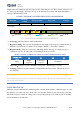
Scan command [A5 60] When an external device sends a scan command to X4, X4 goes into scan mode and feeds back point cloud data. The reply message is: A5 5A 05 00 Start 00 40 Length ‥‥ 81 Mode Type code Content FIG 4 YDLIDAR X4 SCAN COMMAND The 6th byte of which the high 2 is 01, so the answer mode value is 0x1, is a continuous response, ignore the response length, type code is 0x81; The response content is the point cloud data scanned by the system.
Si is sampling data. Sampling data is set to E5 6F. Since the system is in the little-endian mode, the sampling point S = 0x6FE5, and it is substituted into the distance solution formula, which yields Distance = 7161.25mm. Angle analysis: The angle data is stored in FSA and LSA. Each angle data has the following data structure. C is the check digit and its value is fixed at 1.
XOR𝑒𝑛𝑑 is an XOR formula that represents an XOR of the number of elements in the element from 1 subscript 1 to end. But the XOR satisfies the commutative law, and the actual solution may not need to follow the XOR order of this article. Stop command [A5 65] When the system is in the scanning state, X4 has been sending out point cloud data. If you need to close the scan at this time, you can send this command to stop the system from scanning.
Health status [A5 91] When the external device sends the Get Device Health Status command (A5 91) to X4, X4 will feedback the device's status code. The reply message is: A5 5A 03 00 Start 00 00 Length ‥‥ 06 Mode Type code Content FIG 10 YDLIDAR X4 DEVICE HEALTH According to the protocol resolution: response length = 0x00000003, answer mode = 0x0, type code = 0x06. That is, the number of response content bytes is 3. The response is a single response and the type code is 06.
In this way, the motor and ranging functions are turned off, and the entire system is in the lowest power standby state. Motor speed control Users can change the scanning frequency to meet the needs according to actual needs. By changing the input voltage of the M_SCTP pin or changing the duty cycle of the input PWM signal, the motor speed can be controlled (for specific control methods, refer to the data sheet). www.ydlidar.