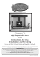
Yeoman CL High Output Boiler Stove YM-CL8HB Instructions for Use, Installation and Servicing For use in GB & IE (Great Britain and Republic of Ireland). This appliance has been certified for use in countries other than those stated. To install this appliance in these countries, it is essential to obtain the translated instructions and in some cases the appliance will require modification. Contact Stovax for further information.
CONTENTS APPLIANCE COMMISSIONING CHECKLIST 3 COMMISSIONING 31 USER INSTRUCTIONS MAINTENANCE & SERVICING 32 General Points Using the Appliance for the first time Recommended Fuels Lighting the Appliance Running the Appliance Burning Tips Ash Removal Woodburning Extended Burning Over-Firing Chimney Fire General Cleaning Cleaning Glass Chimney Sweeping Care of Stove Seasonal Use Troubleshooting Tips 4 4 6 6 7 8 9 10 11 11 11 12 12 12 12 13 13 13 Annual Service Removal of Log Guard Removal of Baffle Fit
APPLIANCE COMMISSIONING CHECKLIST To assist us in any guarantee claim please complete the following information:- Retailer appliance was purchased from Name:.................................................................................................................................................................. Address:................................................................................................................................................................ . ....................
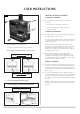
USER INSTRUCTIONS SERIAL NUMBER 1. General POINTS 1.1 1.13 This number is required when ordering spare parts or making warranty claims. It is found on the appliance data plate. Before use of this appliance please read these instructions fully. 1 The appliance must be fitted by a registered installer*, or approved by your local building control officer. 1.2 All local regulations, including those referring to national and European Standards need to be complied with when installing the appliance. 1.
USER INSTRUCTIONS HEATING SYSTEM controls 2 CONTROLS, GENERAL 1.18 The controls fitted to the system will provide two functions: —To control the comfort level in the house. —To maintain safety in the event of misuse or mechanical failure. COMFORT CONTROLS 1.19 A programmable timer switches the pump on when heat is required and off when it is not. The timer, when combined with a room thermostat and / or thermostatic radiator valves, enhances the comfort levels in the house.
USER INSTRUCTIONS 2.6 WARNING Properly installed, operated and maintained this appliance will not emit fumes into the room. NOTE - THIS CONDENSATION IS NORMAL DURING FILLING AND DOES NOT INDICATE A FAULTY OR LEAKING STOVE. Occasional fumes from de-ashing and refuelling may occur. NORMAL RUNNING Persistent fume emission is potentially dangerous and must not be tolerated. 2.7 If fume emission does persist: —Open doors and windows to ventilate the room.
USER INSTRUCTIONS 3.2 Solid fuel 5 Burn only anthracite or manufactured briquette smokeless fuels listed as suitable for use with closed heating appliances. Do not burn bituminous coal, ‘petro-coke’ or other petroleum based fuels as this will invalidate the product guarantee. 3.3 Fuel consumption Fuel Consumption Description Yeoman CL 8HB 3.4 Kg/hour Wood Kg/hour Briquette Smokeless fuel 4.8 2.
USER INSTRUCTIONS —Rake the embers evenly over the firebed and open the 5. Running The appliance Airwash control fully for a few minutes before re-fuelling. Burning wood: 5.1 Do not refuel when a large amount of flames are present in the firebox as this could cause smoke or flames to spill into the room. This appliance gives out its heat in two ways: —Directly into the room in which it is fitted through convection and radiation. Close the doors immediately after refuelling.
USER INSTRUCTIONS 5.8 De-ash the firebed before re-fuelling (see User Instructions, Section 7). 6. Burning tips Open the Primary Air Control fully to establish a glowing bed before adding new fuel. 6.1 Burn new fuel at a high temperature (see Diagram 7) for a few minutes before adjusting the Primary Air Control to the desired setting. Refuel little and often for clean, efficient burning. 5.9 Fuel Quality (Wood) Use wood with a moisture content of less than 20%.
USER INSTRUCTIONS Draught is caused by the rising hot air in the chimney when the appliance is lit. 7. ASH REMOVAL Symptoms of poor performance related to flue draught include: —Excessive fuel consumption (high flue draught). —Poor burning control, overheating (high flue draught). —Wind noise from air controls (high flue draught). —Difficulty getting a fire going and keeping it burning well (low flue draught). —Low heat output (low flue draught). —Smoke entering room when doors opened (low flue draught).
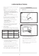
USER INSTRUCTIONS —Fit the plug supplied into the hole where the riddling mechanism is normally located and secure with bolt and clamp (also supplied, see Diagram 15). 8. Wood burning tray 8.1 In order to burn wood continuously in this appliance a Wood Burning Tray should be fitted (see Diagram 12). 15 12 Clamp Plug Bolt Front edge PR8865 PR8862 8.2 Remove the multi-fuel grate from the appliance (see Installation Instructions, Section 5). 8.
USER INSTRUCTIONS Check that the door shuts properly and creates an effective seal. Leaking door seals prevent the appliance working properly. 11. Chimney fire 11.1 If a chimney fire occurs: Do not use aerosol sprays near an operating appliance. —Shut all air controls immediately. —Evacuate the building. 13. CLEANING GLASS —Call the fire brigade. Keep the glass clean with correct use of the Airwash system and good quality fuel. —Do not re-enter the building until it is confirmed safe. 13.
USER INSTRUCTIONS 130°C - 250°C (270°F - 480°F). Failing to close down the Primary Air Control once the appliance has heated up to this range may cause the appliance to exceed the ideal temperature range and to over-fire. Over-firing can cause permanent damage to the appliance and invalidates your warranty. Burn with the Airwash Control fully open for approximately 20 minutes to cure this. 15.
USER INSTRUCTIONS 17.5 All or some of the radiators do not get hot Open up the airwash to make a hotter fire Burning wood Wood is burning too slowly If fitted set the thermostat to a higher setting Burn dryer wood Burn better quality wood Reduce ashbed to 1" thick Burning Solid Mineral fuels Fuel is burning too slowly Open up the primary air to make a hotter fire. If fitted, set the thermostat to a higher setting The fire needs riddling to remove ash. De-ash the fire Empty the ash pan.
TECHNICAL SPECIFICATION YEOMAN Model Yeoman YM-CL8HB Nominal Heat Output Flue Draft at Nominal Heat Output Wood kW 8 Solid Fuel kW 8.6 mm Wg 1.25 inch Wg 0.05 mm 150 inch 6 All Fuels Flue Outlet Size (Top or Rear Option) Minimum Hearth Type Required Constructional = CH CH kg 140 Weight Wood Recommended Fuels Solid Fuels Primary Air (under grate air for full multi-fuel use). • Airwash (for wood burning / clean glass). • Riddling grate system for clean de-ashing.
TECHNICAL SPECIFICATION YEOMAN DIMENSIONS C A D E M G B K N F J L PR8852 Cast Top Plate H PR8753 incl. feet @ 6mm on underside Description A B C D E F (Ø) G H J K L M N Yeoman YM-CL8HB 563 572 363 105 478 153/6" 449 24 441 225 430 224 317 All dimensions are in mm (25.
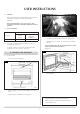
SITE REQUIREMENTS 1. FLUE OR CHIMNEY 1.1 The flue or chimney system must be in good condition. It must be inspected by a competent person and passed for use with the appliance before installation. Products of combustion entering the room can cause serious health risks. 1.2 The following must be checked: 1.4 Suitable access must be provided to enable the collection and removal of debris. 1.5 The flue must be swept and inspected when the appliance is installed. 1.
SITE REQUIREMENTS 1. FLUE OUTLET POSITIONS Terminal Flue Vertical Measurement Horizontal Measurement 150mm max Insulation Adjacent Building The vertical measurement is the lowest from either the point of discharge or 150mm above insulation.
SITE REQUIREMENTS WALLS NEXT TO A HEARTH Solid, non-combustible material e.g.
PRE-INSTALLATION CHECKS 1. Flue Model Yeoman YM-CL8HB Without Liner System Round (diameter) Flue / Chimney Size Without Liner System (square) Minimum Dimension With Liner or Factory Made System (diameter) Flue / Chimney minimum height* mm 150 inch 6 mm 135 inch 5½ mm 150 mm 6 m 4.
PRE-INSTALLATION CHECKS 2. VENTILATION 2.1 Additional ventilation will be required to suit the requirements of Building Regulations. This must be provided using a permanently open air vent, of the size listed, which is positioned so that it is not liable to be blocked both inside and outside the building. 2.2 The appliance will require additional ventilation as listed*: A) Building design permeability greater than 5.0m³ (h.m²). B) Building design permeability less than 5.0m³ (h.m²).
INSTALLATION INSTRUCTIONS 1.1 Legal requirements Before installation and/or use of this appliance please read these instructions carefully to ensure that all requirements are fully understood. Take care when installing the appliance. Careless handling and use of tools can damage the finish and/or area. Choose top or rear flue exit (see Diagram 1). The appliance must be fitted by a registered installer*, or approved by your local building control officer.
INSTALLATION INSTRUCTIONS —Secure with self tapping screw. —Seal the connecting joints. Do not use a 90˚elbow to make this connection. The flue must be installed in accordance with manufacturers instructions. Seal Collar with Fire Cement Self tapping screw PR8009 Tee The flue must be installed in accordance with manufacturers instructions. Flue Pipe 915mm (3ft) Size Stovax Part No. 6" 4602 Size Stovax Part No.
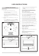
INSTALLATION INSTRUCTIONS 6 3. FITTING AND REMOVAL OF THE BAFFLE No tools are required. 3.1 Front support To maintain efficient combustion the appliance is fitted with a baffle system that allows for secondary combustion (see Diagram 4). Rear support 4 AR2405 Ensure baffle sits on front supports PR8885 3.2 First remove the log guard from the stove to give access to the firebox. 3.3 Use both hands to lift the baffle vertically and slide to one side (see Diagram 5).
INSTALLATION INSTRUCTIONS 10 7 Lift bars to remove PR8875 PR8867 To remove Multi-fuel frames: —Remove Rear Bar (see Diagram 8). —Lift frames from the front. —Remove right hand side first through the front of the 8 stove. —Repeat for the left hand side. 11 PR8868 To remove the Riddling Boss: —Use the 5mm hex key as shown in Diagram 9. PR8876 —Replace in reverse order. 9 Fixing Bolt Riddling Boss 5mm Hex Key PR8870 —Unscrew the boss. —Remove Riddling Cam Bar (see Diagram 10).
INSTALLATION INSTRUCTIONS 6.2 5. HEARTH FIXING 5.1 Place the cast top plate feet down on top of the appliance. —Ensure the cast top is flush with the front and sides of the appliance. If the appliance is to be fixed to the hearth then use the hearth mount locking tabs shown in Diagram 12. —For the top flue version, position the cutout over the flue ring. —Position the appliance where required on the hearth and mark the location of the two fixing holes in the hearth mounts.
INSTALLATION INSTRUCTIONS 3. Hot Water Cylinder CENTRAL HEATING SYSTEM 3.1 1. General This appliance gives out heat in two ways: —Directly into the room in which it is fitted through Fully insulate the tank. convection and radiation. —Hot water to heat radiators and domestic hot water. The water draw off pipes to the taps should be in a dead leg connection from the vent pipe. The installation must comply with building regulations and use best practice advice. 4.
INSTALLATION INSTRUCTIONS 6. Pump 6.1 9. Pump Assisted Central Heating 9.1 Where a pump is fitted into the circuit it should be adjustable so that the flow can match the system requirements. Fit isolation valves to enable removal for servicing. The pump must have at least 1.5 meters of static head. To overcome this problem it is common practice to fit an injector tee where the pumped central heating return re-joins the gravity return from the hot water cylinder.
INSTALLATION INSTRUCTIONS See below typical layout of a pumped central heating hot water circuit with gravity.
NOTE - THIS CONDENSATION IS NORMAL DURING FILLING AND DOES NOT INDICATE A FAULTY OR LEAKING STOVE. Heating system controls CONTROLS GENERAL 1.1 NORMAL RUNNING The controls fitted to the system will provide two functions: 1.9 — To control the comfort level in the house. — To maintain safety in the event of misuse or mechanical failure. COMFORT CONTROLS 1.2 SEASONAL USE This primarily consists of a time clock wired into the pump.
COMMISSIONING When the system has stabilised, write down the new difference between the flow and return temperatures and any which differ from the index radiator by more than 1 degree will need further adjustment, some valves will have been closed too much and others not enough, usually the adjustments need to be only a fraction of a turn at a time. Leave sufficient time for the system to stabilise after each adjustment. COMMISSIONING 1.1 1.2 To commission: — Replace the log retainer.
MAINTENANCE and SERVICING For a complete list of spare parts and accessories contact your Yeoman retailer or call 01392 474011 This is a list of the maintenance products you may need to use: 1. ANNUAL SERVICE 1.1 Task Before the start of the heating season strip, inspect and clean the appliance as detailed: —Allow appliance to cool.
MAINTENANCE and SERVICING 2. REMOVAL OF THE LOG GUARD 2.1 Fixing Screws x 8 To remove the Log guard: —Lift Log Guard clear of the supporting brackets. —Rotate to clear the sides of the door opening. Glass rope seal B Do not use appliance without the log guard in position. 3. FITTING AND REMOVAL OF BAFFLE 4.1 See Installation Instructions, Section 3. 4.
MAINTENANCE and SERVICING —Clean, and re-paint, the rear of the door if required. —Clean the screws with light oil. Seal Length (mm) Door rope seal C 2300 —Coat with high temperature anti-seize grease to aid Door rope seal D 410 Mid door rope seal E 450 future removal. —Carefully wrap glass sealing rope (A) round the sides and —Remove the old rope. bottom edge of the glass. —Scrape old glue from the locating groove.
MAINTENANCE and SERVICING The hinge plate assembly is slotted so it can be moved up, down and sideways by approximately 3mm to adjust the position of the door in relation to the appliance. 7. ADJUSTING DOOR CATCH & HINGES 7.1 To maintain the safe use of your appliance, you may need to adjust the door hinges to ensure the door closes safely and correctly. 7.
SPARE PARTS LIST Ref. No. Product Code 1 2 3 4 5 6 7 8 9 10 11 12 13 14 15 16 17 18 19 20 21 22 CA7669 SM13 CA7651 SM62 ST8-CA7480 ST8-CA7479 ST8-CA7464 ST8-CA7500 MEC8792 RVN-CA7595 ST8-CA7584 MEC8793 ST8-MEC8155 MEC8620 ST8-CA7463 SM19 ME600521 ST8-MEC8802 MEC8625 Drawing No.
SPARE PARTS LIST Ref. No. Product Code Drawing No.
SERVICE RECORDS 1ST SERVICE 2ND SERVICE Date of Service:........................................................................... Date of Service:........................................................................... Next Service Due:....................................................................... Next Service Due:....................................................................... Signed:........................................................................................
A division of Stovax Ltd Falcon Road, Sowton Industrial Estate, Exeter, Devon, England EX2 7LF Tel: (01392) 474500 Fax: (01392) 219932 E-mail: yeoman@stovax.com www.yeoman-stoves.co.