Yeoman CL Free Standing Stove Models: YM-CL3MF / YM-CL5W / YM-CL5MF / YM-CL8W / YM-CL8MF This design is protected under Registered Community Design no's. 001202600-0004 / 001202600-0005 / 001202600-0006 Instructions for Use, Installation and Servicing For use in GB & IE (Great Britain and Republic of Ireland). This appliance has been certified for use in countries other than those stated.
COVERING THE FOLLOWING Models: Models: YM-CL3MF / YM-CL5W / YM-CL5MF / YM-CL8W / YM-CL8MF APPLIANCE COMMISSIONING CHECKLIST 3 COMMISSIONING 24 USER INSTRUCTIONS MAINTENANCE & SERVICING 25 General Points Using the Appliance for the first time Recommended Fuels Lighting the Appliance Running the Appliance Burning Tips Ash Removal Extended Burning Over-Firing Chimney Fire General Cleaning Cleaning Glass Chimney Sweeping Care of Stove Seasonal Use Troubleshooting Tips Smoke Control Kit 4 Annual Service
APPLIANCE COMMISSIONING CHECKLIST To assist us in any guarantee claim please complete the following information:- Retailer appliance was purchased from Name:.................................................................................................................................................................. Address:................................................................................................................................................................ . ....................
USER INSTRUCTIONS 1. General POINTS 1.1 Before use of this appliance please read these instructions fully. The appliance must be fitted by a registered installer*, or approved by your local building control officer. 1.2 All local regulations, including those referring to national and European Standards need to be complied with when installing the appliance. 1.3 Only use for domestic heating in accordance with these operating instructions. 1.4 You must burn only approved fuels.
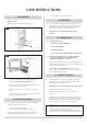
USER INSTRUCTIONS CLOSE Airwash Control —All open flued appliances can be affected by temporary atmospheric conditions which may allow fumes to enter the house. Because of this an electronic carbon monoxide detector conforming to the latest edition of BSEN50291 must be fitted in the same room as the appliance. The existence of an alarm must not be considered a substitute for ensuring regular servicing and maintenance of the appliance and chimney system.
USER INSTRUCTIONS —Place firelighters or paper and dry kindling wood on the grate. Do not burn construction timber, painted, impregnated / treated wood, manufactured board products or pallet wood. 3.2 —Light the paper or firelighters (see Diagram 5). Solid fuel Burn only anthracite or manufactured briquette smokeless fuels listed as suitable for use with closed heating appliances. Do not burn bituminous coal, ‘petro-coke’ or other petroleum based fuels as this will invalidate the product guarantee.
USER INSTRUCTIONS 5.6 Air Inlets Mutli-fuel Stove Burning Solid Fuel Solid Fuel can only be burned in a multi-fuel stove. Only for use with recommended fuels (see User Instructions, Section 3). Set air controls (see Diagram 9). Airwash: 50% Log Guard PR8742 —Close the door. 5. Running The appliance 5.1 Burning Wood —Close the Primary Air control and use the Airwash to control the temperature (see Diagram 8). Airwash: Adjust Primary Air: 50% PR8727 5.
USER INSTRUCTIONS 5.12 Do not burn bituminous coal, ‘petro-coke’ or other petroleum based fuels, as this invalidates the product guarantee. Draught is caused by the rising hot air in the chimney when the appliance is lit. Symptoms of poor performance related to flue draught include: —Excessive fuel consumption (high flue draught). —Poor burning control, overheating (high flue draught). —Wind noise from air controls (high flue draught).
USER INSTRUCTIONS —Use smokeless fuel or small, thick logs. 7. ASH REMOVAL 7.1 9. OVER-FIRING Multi-fuel stove Riddle with the tool provided (see Diagram 9). 9.1 Do not over-fill with fuel or run at high temperatures for long periods or over-firing can occur. If the flue pipe, flue collar or top plate glow red the appliance is over-firing. Close the air controls to reduce the temperature. 9.2 Over-firing can cause permanent damage to the appliance. 10. Chimney fire 10.
USER INSTRUCTIONS Check for obvious build up of soot, ash or debris above the flue baffle(s) (these can be found in the upper part of the firebox). Use a torch if necessary. 13.2 The chimney, any connecting flue pipe and the appliance flue ways, if incorporated, must be regularly cleaned. 13.3 Ensure adequate access for cleaning where it is not possible to sweep through the chimney. If there are any signs of a build up of debris above the flue baffle(s) either: 13.
USER INSTRUCTIONS This is caused by burning damp wood and running the appliance at too low a temperature. 16. Troubleshooting tips 16.1 Stove glass blackening This has four possible causes: Use well seasoned wood and operate the appliance within the ideal temperature range. 1. Incorrect use of Airwash See User Instructions, Sections 1, 4 and 5 for the correct use of the air controls. Tar is a major cause of chimney fires.
TECHNICAL SPECIFICATION YEOMAN Yeoman CL3 Yeoman CL5 Yeoman CL8 Model Wood kW 3.75 4.9 8 Solid Fuel kW 3.75 4.9 8.6 mm Wg 1.25 1.25 1.25 inch Wg 0.05 0.05 0.05 Wood g/s 3.8 2.6 7.0 Solid Fuel g/s 2.9 3.2 7.
TECHNICAL SPECIFICATION YEOMAN DIMENSIONS C A D F K E B G J PR8642 Cast Top Plate H PR8753 incl. feet @ 6mm on underside Description Model A B C D E F (Ø) G H J K Yeoman CL3 YM-CL3MF 360 510 306 93 416 128/5" 400 22 240 195 435 518 303 90 424 128/5" 408 24 315 199 563 572 363 105 478 153/6" 449 24 441 225 Yeoman CL5 Yeoman CL8 YM-CL5W YM-CL5MF YM-CL8W YM-CL8MF All dimensions are in mm (25.
SITE REQUIREMENTS 1. FLUE OR CHIMNEY 1.1 The flue or chimney system must be in good condition. It must be inspected by a competent person and passed for use with the appliance before installation. Products of combustion entering the room can cause serious health risks. 1.2 The following must be checked: 1.4 Suitable access must be provided to enable the collection and removal of debris. 1.5 The flue must be swept and inspected when the appliance is installed. 1.
SITE REQUIREMENTS 1. FLUE OUTLET POSITIONS Terminal Flue Vertical Measurement Horizontal Measurement 150mm max Insulation Adjacent Building The vertical measurement is the lowest from either the point of discharge or 150mm above insulation.
SITE REQUIREMENTS WALLS NEXT TO A HEARTH Solid, non-combustible material e.g.
PRE-INSTALLATION CHECKS 1.
PRE-INSTALLATION CHECKS 2.7 Ventilation requirements in the UK are as shown in the table below: 2.10 Site the vents where cold draught is unlikely to cause discomfort. This can be avoided by placing vents near ceilings or close to the appliance, see diagram below. A) Traditionally Built Homes — Where the leakage is greater than 5m3/hour/m2.
INSTALLATION INSTRUCTIONS 1.1 Legal requirements Before installation and/or use of this appliance please read these instructions carefully to ensure that all requirements are fully understood. Take care when installing the appliance. Careless handling and use of tools can damage the finish and/or area. Choose top or rear flue exit (see Diagram 1). The appliance must be fitted by a registered installer*, or approved by your local building control officer.
INSTALLATION INSTRUCTIONS —Secure with self tapping screw. —Seal the connecting joints. Do not use a 90˚elbow to make this connection. The flue must be installed in accordance with manufacturers instructions. Seal Collar with Fire Cement Self tapping screw PR8009 Tee The flue must be installed in accordance with manufacturers instructions. Flue Pipe 915mm (3ft) Size Stovax Part No. ‡5" 4502 6" 4602 Size Stovax Part No.
INSTALLATION INSTRUCTIONS —Pull the baffle forward to disengage the rear edge from the location above air inlet holes. 3. FITTING AND REMOVAL OF THE FIREBRICKS 3.1 Remove the firebricks as part of the routine maintenance. This can be carried out without the use of tools. 3.2 Allow the appliance to cool fully before removing firebricks. 3.3 Take care when handling, as bricks can become fragile after use. Life span depends on the type of fuels burnt and the level of use.
INSTALLATION INSTRUCTIONS 6. HEARTH FIXING 6.1 If the appliance is to be fixed to the hearth then use the hearth mount locking tabs shown in Diagram 10. —Position the appliance where required on the hearth and mark the location of the two fixing holes in the hearth mounts. —Drill the required sized holes into the hearth. —Use suitable fasteners to fix in place. Main grate 5.4 PR8846 Remove riddling slider and connecting rod by unscrewing the 6 x M8 nuts using a 10mm A/F spanner (see Diagram 9).
INSTALLATION INSTRUCTIONS 7. CAST TOP 8. co alarms This appliance can be fitted with an optional cast top plate. The type of plate will depend on whether the appliance is installed with a top* or rear flue exit. Top Flue Rear Flue Yeoman CL3 YM-CL3CT YM-CL3CTR Yeoman CL5 YM-CL5CT YM-CL5CTR Yeoman CL8 YM-CL8CT YM-CL8CTR All open flued appliances can be affected by temporary atmospheric conditions which may allow fumes to enter the house.
COMMISSIONING —Explain the cleaning and routine maintenance COMMISSIONING 1.1 requirements. —Explain the requirement to use a suitable fireguard To commission: —Replace the baffle and log guard. when children, elderly or infirm persons are near the appliance. —Check the door alignment and catch operation and —Record retailer/supplier and installer details in adjust if required (see Maintenance & Servicing, Section 7).
MAINTENANCE and SERVICING For a complete list of spare parts and accessories contact your Yeoman retailer or call 01392 474011 —To refresh painted finishes use Stovax Riva Midnight 1. ANNUAL SERVICE 1.1 black paint. 1.2 Before the start of the heating season strip, inspect and clean the appliance as detailed: —Allow appliance to cool. Use genuine Stovax replacement parts to keep the appliance in safe, efficient working order.
MAINTENANCE and SERVICING 1.5 1.6 During this time the appliance may give off some unpleasant odours. Keep the room well ventilated to avoid a build-up of fumes. Fixing Screws x 8 Your Yeoman retailer can carry out service and maintenance. 2. REMOVAL OF THE LOG GUARD 2.1 Glass rope seal B To remove the Log guard: —Lift Log Guard clear of the supporting brackets. —Rotate to clear the sides of the door opening. Do not use appliance without the log guard in position. 3.
MAINTENANCE and SERVICING —Clean, and re-paint, the rear of the door if required. Length (mm) —Clean the screws with light oil. Seal Yeoman CL3 Yeoman CL5 Yeoman CL8 Door rope seal C 1400 1600 2300 Door rope seal D 175 175 410 Mid door rope seal E (CL8 models only) n/a n/a 450 —Coat with high temperature anti-seize grease to aid future removal. —Carefully wrap glass sealing rope (A) round the sides and bottom edge of the glass.
MAINTENANCE and SERVICING 7. ADJUSTING DOOR CATCH & HINGES 7.1 To maintain the safe use of your appliance, you may need to adjust the door hinges to ensure the door closes safely and correctly. 7.2 To adjust the door catch: M6 screws x4 —Open the door to gain access to the catch. —Use a 13mm A/F spanner to loosen the half lock nuts either side of the appliance body. This will allow the dome catch to rotate in and out (see diagram below).
SPARES LIST YM-CL3MF Ref. No. Product Code 1 2 3 4 5 6 7 8 9 10 11 12 13 14 15 16 17 18 CA7668 SS13 SM15 CE7810 CA7618 SMN37 SMN36 MEC8818 MEC8793 SMN25 MEC8608 MEC8788 MEC8644 RA502300 CA7629 ME600599 SMN26 MEC8607 YM-CL8MF Drawing No. (if different) MEC7026 ME7027 CA7050 CA7049 CA7031 RA7117 Description Ref. No.
SPARES LIST YM-CL8W YM-CL5W Ref. No. Product Code 1 2 3 4 5 6 7 8 9 10 11 12 CA7668 SS13 SM15 CE7812 CA7645 CA7630 CA7664 MEC8628 S5.26 ME600599 CE7817 MEC8782 Drawing No. (if different) MEC7026 ME7027 RA7239 Description Ref. No.
SPARES LIST YM-CL3 YM-CL5 cont. Ref. No. Product Code Drawing No. (if different) 1 2 3 CA7597 MEC8619 FA500024 4 FA9508 5 6 7 8 9 10 11 12 FA500025 CA7635 MEC8636 ME600392 ME600456 CA7634 CA7614 N/A 13 5000 / 4670 CE7717 ROPE SEAL (BLACK) Ø14MM X 175MM (4670) AVAILABLE IN 2M & 25M 13 5000 / 4670 CE7729 ROPE SEAL (BLACK) Ø14MM X 1400MM (4670) AVAILABLE IN 2M & 25M FA500016 Description Ref. No. Product Code Drawing No.
SERVICE RECORDS 1ST SERVICE 2ND SERVICE Date of Service:........................................................................... Date of Service:........................................................................... Next Service Due:....................................................................... Next Service Due:....................................................................... Signed:........................................................................................
A division of Stovax Ltd Falcon Road, Sowton Industrial Estate, Exeter, Devon, England EX2 7LF Tel: (01392) 474500 Fax: (01392) 219932 E-mail: yeoman@stovax.com www.yeoman-stoves.co.