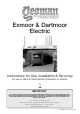
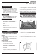
Exmoor & Dartmoor Electric Instructions for Use, Installation & Servicing For use in GB & IE (Great Britain & Republic of Ireland). IMPORTANT THE OUTER CASING, FRONT AND GLASS PANEL BECOME EXTREMELY HOT DURING OPERATION AND WILL RESULT IN SERIOUS INJURY AND BURNS IF TOUCHED. IT IS THEREFORE RECOMMENDED THAT A FIREGUARD COMPLYING WITH BS 8423:2002 IS USED IN THE PRESENCE OF YOUNG CHILDREN, THE ELDERLY OR INFIRM. For use with 230v 50Hz electricity supply only.
Contents Covering the following models: Model Code Exmoor - Small YM-E9001FLA Dartmoor - Single Door YM-E5201FLA Dartmoor - Double Door YM-E5202FLA User Instructions........................................................3. 1. 2. 3. 4. Important Information & Health and Safety............................. 3 Operating Instructions............................................................. 3 Maintenance............................................................................
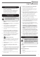
User Instructions How to use these instructions The contents of Sections 1, 2 and 3 apply to all the models in our Electric Range. The content of Section 4, Remove and Replace Door, gives different instructions for each model type. 1.12 Where the electricity supply cable has to pass through a fire place, stone surround etc. ensure suitable rubber bushes are fitted at possible wear points. 1.
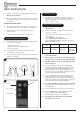
User Instructions 2.3 Dispose of old batteries at an appropriate recycling facility. Standby On/Off When using the handset: 2.11 2.4 Ensure the handset is pointed at the infrared sensor located behind the flame effect screen at the back of the inside of the appliance. Turning On the Appliance LOCATION OF POWER SWITCH 2.5 The appliance is in Standby mode when the power is switched on via the manual control panel. You must have this power supply ON (—) before using the manual or remote controls (see 2.
User Instructions Thermostatic Control 2.21 The appliance is fitted with a thermostat, see Diagram 1, which can control the room temperature between approximately 9˚C and 34˚C. The edge of the thermostat control dial is numbered 1 - 9 with 1 being the coolest setting and 9 being the warmest. If the room temperature is too high turn the thermostat dial in an anti-clockwise direction. If the room temperature is too low turn the dial in a clockwise direction. CLEANING LOG MOULDING 3.
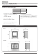
Installation Instructions Technical Specification These instructions cover the following models: Model Code Exmoor - Small YM-E9001FLA Dartmoor - Single Door YM-E5201FLA Dartmoor - Double Door YM-E5202FLA These appliances have 3 modes of operation: — — — Flame effect only - with brightness and flame colour adjustment Flame effect + 1kW heating Flame effect + 2kW heating A 230v 13amp 50Hz supply is required ALL INGLENOOK FIREPLACE OPENINGS: For all models the dimensions required for an ingle
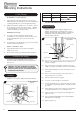
Installation Instructions 1. Fitting Appliances Most appliances are heavy and do not require anchoring to the hearth or floor, but in certain circumstances the appliance can become unstable e.g. when leaning on the appliance. If this is likely, secure the appliance to the hearth or floor with suitably strong fixings. 1.1 Position the appliance ensuring all appropriate clearances are observed. 1.2 Mark the position of the holes in the fixing brackets attached to the inside of the rear legs. 1.
Servicing Instructions 1. Fault Finding Live Wire No illumination or uneven lighting: 1.1 1.2 Brown Terminal L / RED Neutral Wire Blue Terminal N / BLACK Earth Wire Green & Yellow Stripes Check the heater is working. If YES, one or more of the LED boards will need replacing. This must be undertaken by a suitably qualified person (see Servicing Requirements). If NO, first change the 13amp fuse for one known to work.
Servicing Instructions 4.4 Dispose of the board at an appropriate recycling centre. 4.5 THIS APPLIANCE MUST ONLY BE SERVICED BY A SUITABLY QUALIFIED PERSON. To connect the new LED board push the fasteners through the ready drilled holes and ensure that all wires are correctly connected. BEFORE UNDERTAKING ANY WORK ON THE APPLIANCE: 5. Replacing the Printed Circuit Board 3. Servicing Requirements 3.1 Switch off the appliance and isolate it from the mains by unplugging the unit. 5.
Servicing Instructions 6.2 Disconnect the 2 x wires connecting the 2 x 'flying' LEDs to the front LED board, noting their orientation. 6.3 Lift and rotate the motor unit to give access to the rear LED board. 6.4 Disconnect both wires from the rear LED board, noting the orientation. 6.5 Unplug the cables connecting the motor unit and the PCB. 6.6 The motor and effects unit can now be removed and replaced as a whole unit. 6.7 9. Replacing the Heater Assembly 9.
Servicing Instructions 9.5 Disconnect the 4 x coloured wires running from the firebox to the heater assembly, see Diagram 11 noting the orientation. 11 Disconnect wires Disconnect wires 9.6 Fit new heater assembly, ensuring all wires are correctly attached and the heater is secured to its casing using 4 x screws. 9.7 Reattach heater casing to bottom of firebox using 5 x screws. 9.8 Relocate the appliance to its original position and replace any loose top plates or panels.
Yeoman Limited, Osprey Road, Sowton Industrial Estate, Exeter, Devon, England EX2 7JG Technical Customer Services: (01392) 261950 Fax: (01392) 261951 E-mail: info@Yeoman.