5000 SERIES STALK DEVASTATOR CORN STALK ROLLER *PATENTED* 5000-025, 5000-026, 5000-027, 5000-028 OPERATOR’S MANUAL PART IDENTIFICATION 2565-785 – 08/2014 YETTER MANUFACTURING CO. FOUNDED 1930 Colchester, IL 62326-0358 Toll free: 800/447-5777 309/776-3222 (Fax) Website: www.yetterco.com E-mail: info@yetterco.
FOREWORD You’ve just joined an exclusive but rapidly growing club. For our part, we want to welcome you to the group and thank you for buying a Yetter product. We hope your new Yetter products will help you achieve both goals-increase your productivity and increase your efficiency so that you may generate more profit. This operator’s manual has been designed into four major sections: Foreword, Safety Precautions, Installation Instructions and Parts Breakdown.
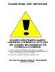
BE ALERT! YOUR SAFETY IS INVOLVED. WATCH FOR THIS SYMBOL. IT POINTS OUT IMPORTANT SAFETY PRECAUTIONS. IT MEANS “ATTENTION---BECOME ALERT!” It is your responsibility as an owner, operator, or supervisor to know and instruct everyone using this machine at the time of initial assignment and at least annually thereafter, of the proper operation, precautions, and work hazards which exist in the operation of the machine in accordance with OSHA regulations.
PLEASE READ, VERY IMPORTANT SECURE CORN HEADER AGAINST UNWANTED LOWERING BY APPLYING THE LOCKING MECHANISM ON THE HYDRAULIC CYLINDERS! 1. ATTACH HEAD TO COMBINE, LOCK HEAD TO COMBINE 2. RAISE THE HEAD OFF THE GROUND AND ENGAGE THE SAFETY STOP ON THE FEEDER HOUSE CYLINDER. 3. TURN OFF COMBINE ENGINE AND REMOVE KEY. FOLLOW THE INSTRUCTIONS OF THE COMBINE MANUFACTURER.
PLEASE READ, VERY IMPORTANT Subject to the size and weight of the corn header, one or two additional hydraulic cylinders may be required. The combine manufacturer generally keeps the corresponding kits readily available for the dealer. Subject to the design of the corn header and carrying capacity of the different combines, the steering axle may require the fitting of additional weights and the rear tires might need to be filled with ballast. FOLLOW THE INSTRUCTIONS OF THE COMBINE MANUFACTURER.
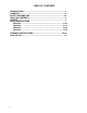
TABLE OF CONTENTS INTRODUCTION…………………………………………………………….…..2 WARRANTY………………………………………………………………….….2 SAFETY INFORMATION…………………………………………………….2-5 TABLE OF CONTENTS…………………………………………………….….6 TORQUE………………………………………………………………………....7 PARTS IDENTIFICATON 5000-025………………………………………………………………….8-10 5000-026………………………………………………………………...11-13 5000-027…………………………………………………………………14-16 5000-028…………………………………………………………………17-19 ASSEMBLY INSTRUCTIONS…………………………………………….20-26 LOCK UP PIN…………………………………………………………………..
BOLT TORQUE Mounting bolts and hardware All hardware used on the 5000 Devastator is Grade 5 unless otherwise noted. Grade 5 cap screws are marked with three radial lines on the head. If hardware must be replaced, be sure to replace it with hardware of equal size, strength and thread type. Refer to the torque values chart when tightening hardware. Important: Over tightening hardware can cause as much damage as when under tightening.
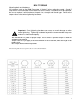
PARTS IDENTIFICATION 8
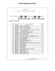
PARTS IDENTIFICATION 9
PARTS IDENTIFICATION 10
PARTS IDENTIFICATION 11
PARTS IDENTIFICATION 12
PARTS IDENTIFICATION 13
PARTS IDENTIFICATION 14
PARTS IDENTIFICATION 15
PARTS IDENTIFICATION 16
PARTS IDENTIFICATION 17
PARTS IDENTIFICATION 18
PARTS IDENTIFICATION 19
ASSEMBLY INSTRUCTIONS STEP 1. ATTACH THE 5000-202 MOUNT BRACKETS TO THE FRAME USING THE 5/8” X 6” BOLTS, CLAMPS AND LOCK HEX NUTS. NOTE: DO NOT FULLY TIGHTEN HARDWARE UNTIL THE PIVOT ARMS ARE INSTALLED AT STEP 4.
ASSEMBLY INSTRUCTIONS STEP 2. ATTACH THE 5000-309 SUPPORT STRAPS USING THE 1/2" X 2 CARRIAGE BOLTS AND FLANGE LOCK NUTS.
ASSEMBLY INSTRUCTIONS STEP 3. INSTALL THE 5000-323 LOCK UP PIN IN THE STORAGE LOCATION ON THE MOUNT BRACKETS SECURE WITH THE HAIRPIN CLIPS.
ASSEMBLY INSTRUCTIONS STEP 4. ATTACH THE PIVOT ARMS TO THE MOUNT BRACKETS USING THE 5/8” X 3 BOLTS, PIVOT BUSHINGS, AND LOCK HEX NUTS. FULLY TIGHTEN ALL THE HARDWARE AT THIS TIME, MOUNTING BOLTS INCLUDED.
ASSEMBLY INSTRUCTIONS STEP 5. INSTALL THE PUSH RODS INTO THE MOUNT BRACKETS THEN ATTACH TO THE PIVOT ARMS WITH THE 5/8” SHOULDER BOLTS, WASHERS AND ½” JAM LOCK HEX NUTS. NOTE: THE WASHERS ARE INSTALLED ON EACH SIDE OF THE “EYE” OF THE PUSH ROD. NOW INSTALL THE COMPRESSION SPRINGS, SPRING BUSHINGS AND ¾’ LOCK HEX NUTS.
ASSEMBLY INSTRUCTIONS STEP 6. ATTACH THE ROLLER MOUNT TO THE PIVOT ARMS THEN INSTALL THE 1/2” X 3-3/4” BOLTS, SPACERS AND LOCK NUTS. SLIDE THE ROLLER MOUNT SIDE TO SIDE TO CLEAR THE END OF THE CORN HEAD. FULL TIGHTEN HARDWARE.
ASSEMBLY INSTRUCTIONS STEP 7. INSTALL THE SHIMS AND BEARINGS ONTO THE ROLLERS. NOTE: THE EXTENDED RACE ON THE BEARING WILL FACE TOWARD THE ROLLER. ATTACH THE BEARING/ROLLER ASSEMBLY TO THE PIVOT ARMS USING THE ½” X 2-1/2” BOLTS AND 1/2'” LOCK HEX NUTS.
Our name Is getting known Just a few years ago, Yetter products were sold primarily to the Midwest only. Then we embarked on a program of expansion and moved into the East, the South, the West and now north into Canada. We’re even getting orders from as far away as Australia and Africa. So, when you buy Yetter products . . .you’re buying a name that’s recognized. A name that’s known and respected.