Document No. 00BNO9132-# / 23.02.
VARMAX TWIN - Installation, Use and Maintenance SOMMAIRE 1. AVERTISSEMENTS ET RECOMMANDATIONS ....................................................................4 1.1. 1.2. 1.3. 1.4. 1.5. 1.6. Limite de fourniture de la VARMAX TWIN..................................................................................................... 4 Transport et stockage....................................................................................................................................
VARMAX TWIN - Installation, Use and Maintenance 1. WARNINGS AND RECOMMENDATIONS PLEASE READ THIS MANUAL CAREFULLY BEFORE INSTALLING, MAINTAINING AND USING THE BOILER. IT CONTAINS IMPORTANT SAFETY INFORMATION. 1.1.
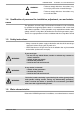
VARMAX TWIN - Installation, Use and Maintenance ! WARNING: Failure to comply with these instructions may cause injury and serious material damage. WARNING: Failure to comply with these instructions may cause electrocution. 1.4. Qualification of personnel for installation, adjustment, use and maintenance The operations to install, adjust and maintain the boiler must be carried out by qualified and approved professionals in accordance with current local and national regulations.
VARMAX TWIN - Installation, Use and Maintenance 2. APPROVALS 2.1. Compliance with European Directives - Low voltage (2006/95/CE) This appliance is not intended for use by persons (including children) whose physical, sensory or mental abilities are reduced, or persons without experience or knowledge, unless they have been able to benefit, through someone responsible for their safety, from supervision or prior instruction concerning the use of the appliance.
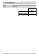
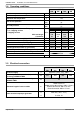
VARMAX TWIN - Installation, Use and Maintenance 2.5. Gas supply pressures INFORMATION: The pressures provided below must be taken at the input to the gas valve (20 mbar).
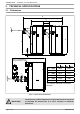
VARMAX TWIN - Installation, Use and Maintenance 3. TECHNICAL SPECIFICATIONS 3.1. Dimensions D A 450±10 45 min 60 max E B 3° C sleeve for safety valve on each generator (F 1"1/4) MODELS 3° øF 550 640 780 900 A (mm) 2059 2259 B (mm) 1877 2023 C (mm) 2032 2114 D (mm) 2519 2749 E (mm) 1500 1590 Ø F (mm) 250 300 The diameter indicated is the interior diameter.
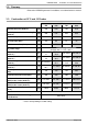
VARMAX TWIN - Installation, Use and Maintenance 3.2. Doorway Refer to the VARMAX generator's installation, use and maintenance manual. 3.3. Combustion at 15°C and 1013 mbar MODELS 550 640 780 900 Nominal power Pn (80/60°C) kW 536 624 762 878 Nominal power when condensing Pn (50/30°C) kW 580 676 830 956 Rated heat input Qn kW 550 640 780 900 Min heat input Qmin kW 66 66 87 87 Gas flow rate at Pn (15 °C) * m3/h 58.2 67.72 82.6 95.
VARMAX TWIN - Installation, Use and Maintenance 3.4.
VARMAX TWIN - Installation, Use and Maintenance 4. INSTALLATION 4.6. Positioning the air filters and the filtering layers ! IMPORTANT: The air filters provided with the generators MUST be installed. The air filters must be installed before the gas lines are connected. Refer to the VARMAX generator's installation, usage and maintenance manual, paragraph "4-1 Positioning the air filter and the layer"). 4.7.
VARMAX TWIN - Installation, Use and Maintenance • The 2 VARMAX generators must be positioned horizontally using a spirit level to enable effective gas release for the exchanger body (use the base as the reference surface). ! IMPORTANT: • The space between the 2 VARMAX generators must be 450±10 mm. • A 2 cm free space must also be left above the side panels to allow for their disassembly and reassembly. • The 2 generators must be in the same alignment and on the same horizontal level.
VARMAX TWIN - Installation, Use and Maintenance 4 Teflon plates are provided to facilitate the introduction of the 2 generators in relation to each other: • Put one plate under each of the 4 feet of the generator to be moved, Teflon plates (x4) figure 4 - Teflon plate positioning • Position the generator, • Remove the Teflon plates. 4.8. Installing the LPB bus cable trays Position the 2 trays for the LPB bus cable on the rear of the 2 generators and secure them using the 4 self-tapping screws provided.
VARMAX TWIN - Installation, Use and Maintenance 4.9. Opening / closing the casing doors Refer to the VARMAX generator's installation, use and maintenance manual. 4.10. Removing the control panels (MMI) Refer to the VARMAX generator's installation, use and maintenance manual. 4.11. Installing / removing the casing doors Refer to the VARMAX generator's installation, use and maintenance manual. 4.12.
VARMAX TWIN - Installation, Use and Maintenance 4.15. Exhaust connection ! IMPORTANT: There is a specific connection for the exhausts to the VARMAX TWIN boilers. Do not refer to the VARMAX generator's installation, use and maintenance manual. The size of the chimney pipes must be determined taking account of combustion gas pressure on boiler output equal to 0 Pa (see table § 3.3).
VARMAX TWIN - Installation, Use and Maintenance MODELS 550 - 640 kW 780 - 900 kW ITEM 1 2 3 4 5 6 7 8 9 10 11 DESCRIPTIONS QTY AC-250-180 AC-300-200 Offset increase 2 ED 250-250 CD ED 250-300 CD Straight element length 250 4 EC 90-250 CD EC 90-300 CD 90° curved element 2 ER 26/40 250 CD ER 26/40 300 CD Adjustable element length 260-400 2 T 135-250 CD T 135-300 CD T 135° 2 EPMF 250 EPMF 300 Measurement element 1 ER 55/90 250 ER 55/90 300 Adjustable element length 550-900 1 CE
VARMAX TWIN - Installation, Use and Maintenance 4.15.2. Connection to a B23 chimney B23 type connection: Air from the installation premises, gas evacuation through the roof via a natural draft pipe. ! IMPORTANT: Check that the boiler installation premises have high and low ventilation, that it conforms to current regulations and that it is not obstructed. The size of the chimney pipes must be determined taking account of combustion gas pressure on boiler output equal to 0 Pa (see table § 3.3).
VARMAX TWIN - Installation, Use and Maintenance MODELS Exhaust duct height in linear metres (ml) (in 50/30°C operating regime) ø connection ø duct 300 mm 350 mm 350 mm 400 mm 550 15 to 50 3 to 50 -- -- 640 16 to 50 3 to 50 -- -- 780 -- -- 15 to 50 5 to 50 900 -- -- 33 to 50 6 to 50 250 mm 300 mm ! WARNING: The values below are provided for information purposes. They must be checked by calculation.
VARMAX TWIN - Installation, Use and Maintenance MODELS Exhaust duct height in linear metres (ml) (in 50/30°C operating regime) ø connection ø duct 250 mm 300 mm 250 mm 300 mm 550 1 to 100 -- 640 1 to 100 -- 780 -- 1 to 100 900 -- 1 to 100 ! WARNING: The values below are provided for information purposes. They must be checked by calculation. ! WARNING: The VARMAX TWIN flue must not be made to support the exhaust duct's weight. 4.16.
VARMAX TWIN - Installation, Use and Maintenance In accordance with the diagram, it is imperative to fit the boiler and its installation with the following components: • powered isolating valve (with an end of run contact*) on the flow tapping on each generator's main exchanger, • balancing / isolating valve on each generator's return tapping, • anti-return flap, • filters, • mud cup, • expansion vessel, • effective drain mechanism, • safety valve set at 6 bars, on each generator, sized according to each ge
VARMAX TWIN - Installation, Use and Maintenance 4.16.2. Hydraulic connection using 3 tappings QAZ36 QAZ36 (supplied) (fournie) Main exchanger output câble «bus LPB» LPB bus cable (fourni) (supplied) Hot return (high temperature circuit) Cold return (heated floors and low temperature radiators) B3000 B3000 OCI345 OCI345 (supplied) (fourni) OCI345 OCI345 (supplied) (fourni) figure 10 - Hydraulic connection using 3 tappings 4.16.3.
VARMAX TWIN - Installation, Use and Maintenance 4.17. Gas connection ! IMPORTANT: • The gas must be connected on the 2 VARMAX generators • The use of Propane is prohibited on the VARMAX TWIN boilers. Refer to the VARMAX generator's installation, use and maintenance manual. 4.18. Electrical connection ! ! WARNING: Ensure that the general electrical power supply has been cut off before starting any repair work.
VARMAX TWIN - Installation, Use and Maintenance On each VARMAX generator: - Access the control panel and remove its protective cover. - Secure the module to the boiler controller with the 2 screws supplied. OCI345 Holding screw X11 figure 12 - OCI345 attachment - Connect the communication layer from the OCI345 module to the boiler controller's X11 connector (see previous figure). ! 4.18.1.2. IMPORTANT: Proceed carefully during connection.
VARMAX TWIN - Installation, Use and Maintenance 4.18.2. Connecting the QAZ36 flow sensor 4.18.2.1. Installing the sensor The sensor must be placed in a pocket as close as possible to the 2 generators' common hydraulic output. 4.18.2.2. Electrical connection - Connect the QAZ36 flow sensor to terminal block BX2 on generator 1's NAVISTEM B3000 boiler controller (see chapter 8). ! WARNING: The sensor cable must be run to generator 1's control panel via the "low current" tray.
VARMAX TWIN - Installation, Use and Maintenance 8. HYDRAULIC DIAGRAMS AND CONFIGURATIONS Not communicating No communication with the secondary system VX201 Management of secondary systems by external regulation Communicating via signal 0...
VARMAX TWIN - Installation, Use and Maintenance 1 direct network, no communication with the secondary Diagram VX200 VX201 page 1 / 6 A. MAIN AND VARIANT HYDRAULIC DIAGRAMS B9 Q2 x B10 B3000 B3000 Q1.2 Q1.1 figure 15 - VX200 diagram NON-COMMUNICATING REGULATEUR NON COMMUNICANT REGULATOR B9 x B3000 Q1.1 B3000 B10 Q1.
VARMAX TWIN - Installation, Use and Maintenance Diagrams: VX200 / VX201 page 2 / 6 B. REGULATION ACCESSORIES REQUIRED Appliance reference OCI 345 LPB BUS QAZ 36 QAC 34 Quantity Communication kit Communication cable Output sensor kit Output sensor kit 2 1 1 1 Order No. supplied supplied supplied 059260 C. CUSTOMER'S ELECTRICAL CONNECTION Generator No. 1: If the isolation valve is not equipped with an automatic reset valve, connect the Q1.1 isolating valve's closure contact to Y2.
VARMAX TWIN - Installation, Use and Maintenance Diagrams: VX200 / VX201 230 VAC 50 Hz power supply L N Y1 QX2 N QX3 } LPB bus DB MB Alarm relay } } Isolating valve Q1.2 page 3 / 6 Y2 L N L QX1 N L N AUX2 AUX1 BX2 Gnd BX3 Gnd B3 Gnd B9 Gnd H1 Gnd H5 Gnd valve end } Isolating of run D. SPECIFIC START-UP PROCEDURE Make the accessories' electrical connections. Start up the generator on its own. Make the following settings: On generator No. 1 Line No.
VARMAX TWIN - Installation, Use and Maintenance Diagrams: VX200 / VX201 page 4 / 6 Line No. Value VX200 diagram only: Relay output QX2 (5891) Pump CC1 Q2 BX2 sensor input (5931) Common flow sensor B10 Appliance number Appliance address (6600) 1 Segment number Segment address (6601) 0 Configure pump Q2 All diagrams: Configure TWIN B10 output sensor • Configure as generator No.
VARMAX TWIN - Installation, Use and Maintenance Diagrams: VX200 / VX201 page 5 / 6 E. ELECTRICAL AND HYDRAULIC VALIDATION On generator No. 1 Line No. Value • Flow diagnostic menu Validate the presence of all the generators Gener 1 status (8100) Released / not released Gener 2 status (8101) Released / not released ...............................
VARMAX TWIN - Installation, Use and Maintenance Diagrams: VX200 / VX201 page 6 / 6 F. CONFIGURATION OPTIMISATION On generator No. 1 Heating circuit optimisation: Line No. Value • Heating circuit 1 menu Adjust the reduced setting Reduced setting temperature (712) --- Preselection (500) --- On / off phases (501...
VARMAX TWIN - Installation, Use and Maintenance Secondary networks regulated by external regulator communicating over LPB bus or 0...10V temperature Diagram VX211 page 1 / 6 A. HYDRAULIC DIAGRAM COMMUNICATING REGULATOR REGULATEUR COMMUNICANT 0/10 V SIGNAL TO NAVISTEM B3000 SIGNAL 0/10 V VERS LMS orouLPB BUSsur TO OCI345 bus LPB OCI 345 x Q1.1 B3000 B10 Q1.2 B3000 figure 17 - VX211 diagram B.
VARMAX TWIN - Installation, Use and Maintenance Diagram: VX211 page 2 / 6 C. CUSTOMER'S ELECTRICAL CONNECTION Generator No. 1: INFORMATION: If the isolation valve is not equipped with an automatic reset valve, connect the Q1.1 isolating valve's closure contact to Y2. 230 VAC 50 Hz power supply } LPB bus DB MB L N Y1 QX2 N QX3 } } Isolating valve Q1.
VARMAX TWIN - Installation, Use and Maintenance Diagram: VX211 page 3 / 6 230 VAC 50 Hz power supply L N Y1 QX2 N QX3 } LPB bus DB MB } } Isolating valve Q1.2 Alarm relay Y2 L N L QX1 N L N AUX2 AUX1 BX2 Gnd BX3 Gnd B3 Gnd B9 Gnd H1 Gnd H5 Gnd valve end } Isolating of run D. SPECIFIC START-UP PROCEDURE Make the accessories' electrical connections. Start up the generator on its own. Make the following settings: On generator No. 1 Line No.
VARMAX TWIN - Installation, Use and Maintenance Diagram: VX211 page 4 / 6 Line No. Value For a request via 0...10V input Configure the H1 input H1 input function (5950) H1 voltage 1 value (5953) H1 function value (5954) 10V consumption circ. request 0.0 0 H1 voltage 2 value (5955) 10.
VARMAX TWIN - Installation, Use and Maintenance Diagram: VX211 page 5 / 6 E. ELECTRICAL AND HYDRAULIC VALIDATION On generator No. 1 Line No. Value • Flow diagnostic menu Validate the presence of all the generators Gener 1 status (8100) Released / not released Gener 2 status (8101) Released / not released ............................... For a request via 0...
VARMAX TWIN - Installation, Use and Maintenance Diagram: VX211 page 6 / 6 On generator No. 2 Line No. Value • Inputs/outputs test menu Check the outputs Alarm relay Relay test (7700) Relay output QX1 Isolating valve Q1.2 Relay test (7700) Relay output QX3 Reset the outputs Relay test (7700) No test • Configuration menu Generator 1 inspection No. (6212) 14 Generator 2 inspection No.
VARMAX TWIN - Installation, Use and Maintenance Diagram VX210 VX220 1 network regulated by three-channel valve, DHW production, or 1 direct circuit with constant temperature and flow rate page 1 / 8 A. HYDRAULIC DIAGRAM B9 B1 x Q2 Y1/Y2 B10 x Q1.1 Q1.2 Q3 B3000 B3000 B3 figure 18 - VX210 diagram DIRECT CIRCUIT WITH CIRCUIT DIRECT AVEC CONSTANT TEMPERATURE TEMPERATURE ET DEBIT AND THROUGHPUT CONSTANT B9 B1 x Q2 Q15 Y1/Y2 x B10 Q1.1 B3000 B3000 Q1.
VARMAX TWIN - Installation, Use and Maintenance Diagrams: VX210 / VX220 page 2 / 8 B. REGULATION ACCESSORIES REQUIRED Quantity Appliance reference Order No. 1 AVS 75 059751 2 1 1 1 1 OCI 345 LPB BUS QAZ 36 QAZ 36 QAC 34 supplied supplied supplied 059261 059260 Extension module kit (delivered with a network sensor QAD 36) Communication kit Communication cable Output sensor kit DHW sensor kit (diagram VX210) Output sensor kit C. CUSTOMER'S ELECTRICAL CONNECTION Generator No.
VARMAX TWIN - Installation, Use and Maintenance Diagrams: VX210 / VX220 } Heating circuit No. 1 circulator Q2 } Heating circuit No. 1 mixer valve Y1/Y2 QX21 No. No. page 3 / 8 } Module 1 QX22 BX21 Gnd BX22 Gnd H2 Gnd AVS75 QX23 circuit output sensor } Regulated B1 Generator No. 2: If the isolation valve is not equipped with an automatic reset valve, connect the Q1.2 isolating valve's closure contact to Y2. } Isolating valve Q1.
VARMAX TWIN - Installation, Use and Maintenance Diagrams: VX210 / VX220 page 4 / 8 D. SPECIFIC START-UP PROCEDURE Make the accessories' electrical connections. ! IMPORTANT: Configure the switches on the AVS75 extension module. Start up the generator on its own. Make the following settings: On generator No. 1 Line No. Value • Time and date menu Set the time Hour / minute (1) HH.MM Set the date Day / month (2) DD.
VARMAX TWIN - Installation, Use and Maintenance Diagrams: VX210 / VX220 page 5 / 8 Line No.
VARMAX TWIN - Installation, Use and Maintenance Diagrams: VX210 / VX220 page 6 / 8 the clock is updated correctly. E. ELECTRICAL AND HYDRAULIC VALIDATION On generator No. 1 Line No. Value • Flow diagnostic menu Validate the presence of all the generators Gener 1 status (8100) Released / not released Gener 2 status (8101) Released / not released ...............................
VARMAX TWIN - Installation, Use and Maintenance Diagrams: VX210 / VX220 page 7 / 8 On generator No. 2 Line No. Value • Inputs/outputs test menu Check the outputs Alarm relay Relay test (7700) Relay output QX1 Isolating valve Q1.2 Relay test (7700) Relay output QX3 Reset the outputs Relay test (7700) No test • Configuration menu Generator 1 inspection No. (6212) 14 Generator 2 inspection No.
VARMAX TWIN - Installation, Use and Maintenance Diagrams: VX210 / VX220 page 8 / 8 DHW release (1620) Adjust the DHW release mode Line No. Timer program 4/ DHW Value • Timer programme 4/DHW menu Preselection (560) --- On / off phases (561...
VARMAX TWIN - Installation, Use and Maintenance Diagram VX202 VX212 3 or 4 networks regulated by three-channel valve, with or without DHW production page 1 / 9 A. MAIN AND VARIANT HYDRAULIC DIAGRAMS B12 B9 B1 x x Y5/ Y6 B10 B1.2 x Q6 Q2 Y1/Y2 x B14 x Q20 Y11/ Y12 Q2.2 Y1.2/ Y2.2 B3000 B3000 Q1.2 Q1.1 figure 20 - VX202 diagram B9 B14 B12 B1 Q2 Y1/Y2 B10 x Y5/ Y6 B1.2 x x x Q6 Q20 Q2.2 Y11/ Y12 Y1.2/ Y2.2 x ECS B3000 B3000 Q1.1 Q1.
VARMAX TWIN - Installation, Use and Maintenance Diagrams: VX202 / VX212 page 2 / 9 B. REGULATION ACCESSORIES REQUIRED Extension module kit (delivered with a network sensor QAD 36) Communication kit Communication cable Output sensor kit Output sensor kit DHW sensor kit (VX212 diagram) Quantity Appliance reference Order No. 3 (4) AVS 75 059751 2 1 1 1 1 OCI 345 LPB BUS QAZ 36 QAC 34 QAZ 36 supplied supplied supplied 059260 059261 C. CUSTOMER'S ELECTRICAL CONNECTION Generator No.
VARMAX TWIN - Installation, Use and Maintenance Diagrams: VX202 / VX212 } QX21 No. Heating circuit No. 1 circulator Q2 } No. Heating circuit No. 2 mixer valve Y5/Y6 Heating circuit No. 1 mixer valve Y1/Y2 QX22 } Heating circuit No. 2 circulator Q6 } No. Heating circuit No. 3 mixer valve Y11/Y12 } QX21 No. } No. Heating circuit No. 3 circulator Q20 } Module 1 AVS75 QX23 QX21 No.
VARMAX TWIN - Installation, Use and Maintenance Diagrams: VX202 / VX212 Isolating valve Q1.2 N Y1 QX2 N } Alarm relay } L 230 VAC 50 Hz power supply page 4 / 9 Y2 L QX3 N L QX1 N L N AUX2 AUX1 BX2 Gnd BX3 Gnd B3 Gnd B9 Gnd } LPB bus DB MB H1 Gnd H5 Gnd } Heating circuit No. 4 circulator Q2.2 } Heating circuit No. 4 mixer valve Y1.2/Y2.2 QX21 No. No. QX22 valve end } Isolating of run } Module 1 AVS75 QX23 BX21 Gnd BX22 Gnd H2 Gnd circuit output sensor } Regulated B1.
VARMAX TWIN - Installation, Use and Maintenance Diagrams: VX202 / VX212 page 5 / 9 On generator No. 1 Line No. Value • Time and date menu Set the time Hour / minute (1) HH.MM Set the date Day / month (2) DD.
VARMAX TWIN - Installation, Use and Maintenance Diagrams: VX202 / VX212 page 6 / 9 Line No.
VARMAX TWIN - Installation, Use and Maintenance Diagrams: VX202 / VX212 page 7 / 9 Line No. Value If 4th heating circuit present: • Adjust the heating circuit Heating circuit 1 menu Adjust the comfort setting Comfort setting temperature (710) --- Heating curve slope (720) --- Adjust the curve slope • Switch the heating regime to permanent comfort • Make sure that the communication cable is fully connected between the 2 generators ( ! respect the polarity).
VARMAX TWIN - Installation, Use and Maintenance Diagrams: VX202 / VX212 page 8 / 9 Line No. Value B12 flow sensor Temperature sensor BX21 module 2 (7832) in °C B14 flow sensor Temperature sensor BX21 module 3 (7834) in °C VX212 diagram only: Status of contact H1 (7841) Check the status of contact H1 Closed if the shunt is in place • Configuration menu Check the hydraulic diagram Generator 1 inspection No. (6212) 14 Generator 2 inspection No.
VARMAX TWIN - Installation, Use and Maintenance Diagrams: VX202 / VX212 page 9 / 9 Line No. Value • Heating circuit 1 / 2 / 3 timer programme menu Preselection Preselection (500/520/540) --- Adjust the timer programming On / off phases (501...506) (521...526) (541...
VARMAX TWIN - Installation, Use and Maintenance 9.
ATLANTIC BELGIUM SA SATC ATLANTIC GUILLOT Avenue du Château Jaco, 1 1410 WATERLOO 1 route de Fleurville 01190 PONT DE VAUX Tel.: 02/357 28 28 Fax: 02/351 49 72 Tel.: 03 51 42 70 03 www.ygnis.be Fax: 03 85 51 59 30 www.atlantic-guillot.fr YGNIS AG YGNIS ITALIA SPA Via Lombardia, 56 21040 CASTRONNO (VA) Tel.: 0332 895240 r.a. Fax: 0332 893063 www.ygnis.it Wolhuserstrasse 31/33 6017 RUSWIL CH Tel.