
Operating Instructions and Installation Instructions

Page 16 / 56 00BNO9132-#
VARMAX TWIN - Installation, Use and Maintenance
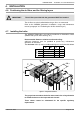
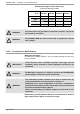
ITEM
MODELS
DESCRIPTIONS QTY
550 - 640 kW 780 - 900 kW
1
AC-250-180 AC-300-200 Offset increase
2
2
ED 250-250 CD ED 250-300 CD Straight element length 250
4
3
EC 90-250 CD EC 90-300 CD 90° curved element
2
4
ER 26/40 250 CD ER 26/40 300 CD Adjustable element length 260-400
2
5
T 135-250 CD T 135-300 CD T 135°
2
6
EPMF 250 EPMF 300 Measurement element
1
7
ER 55/90 250 ER 55/90 300 Adjustable element length 550-900
1
8
CEPL 250 CD CEPL 300 CD Side drain buffer
1
9
SIPHON 1" SIPHON 1" Siphon
1
10
JOINT-CD-250 JOINT-CD-300 Seal
19
11
-- -- Tube of grease for seals
1
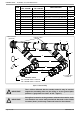
!
IMPORTANT:
The 2 collars delivered with the smoke works kit may be used to
support the assembly either on the ceiling or on the ground (their
position is "greyed out" on each T at 135° - fi gure 7).
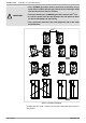
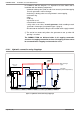
fi gure 7 - Flue assembly
1
2
2
3
4
5
6
7
2
8
9
1
Indicative values
550 - 640 kW models: 1250 mm
780 - 900 kW models: 1350 mm
10
11
Measurement
(upwards)
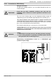
!
IMPORTANT:
During fi nal connection to the generator exhaust outlet nozzles, make
sure that there are not too many mechanical demands on the 2 offset
increases (item 1) as this may create seal losses for the exhaust.
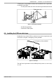
support collars
to condensation
neutraliser