
Operating Instructions and Installation Instructions

Edition: 02 / 2015 Page 19 / 56
VARMAX TWIN - Installation, Use and Maintenance
!
WARNING:
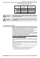
The values below are provided for information purposes. They must
be checked by calculation.
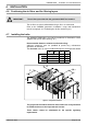
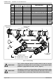
Exhaust duct height in linear metres (ml)
(in 50/30°C operating regime)
ø
connection
250 mm 300 mm
ø
duct
250 mm 300 mm
MODELS
550 1 to 100 --
640 1 to 100 --
780 -- 1 to 100
900 -- 1 to 100
!
WARNING:
The VARMAX TWIN fl ue must not be made to support the exhaust
duct's weight.
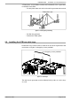
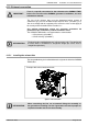
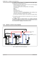
4.16. Hydraulic connection
A water circulation pump integrated into each generator and a smart
regulation logic enable optimum operation up to Pinst/30 (Pinst =
Instant output power expressed as Th/h - 1Th/h = 1.163 kW).
Below this rate of Pinst/30, the generators will continue to operate, but
will gradually reduce their power (shutdown below Pinst/46).
In the main exchanger, as in the condenser on each generator, you must
ensure that the rates recommended in paragraph 3.4 are not exceeded
(i.e. Output power in nominal Th/h generator / 10).
Therefore, a differential pressure valve must be integrated into
the circuit according to the diagam.
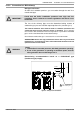
Sizing the pipes connecting the boiler to the installation must be done
carefully, to minimise the pressure losses and so avoid oversized circulating
pumps.
In some cases the diameter of the connection pipes will be greater than the
diameter of the boiler tappings. The diameter increase can then be made
advantageously after the union connectors, the stop valves, and/or the
hydraulic balancing valves.
Tichelmann assembly encourages a natural balance of the fl ow rate between
the 2 generators.
The VARMAX TWIN boilers are equipped with the following elements:
• A drainage valve on each generator's main exchanger,
• A drainage valve on each generator's condenser.