
Operating Instructions and Installation Instructions

Page 20 / 56 00BNO9132-#
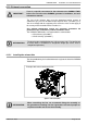
VARMAX TWIN - Installation, Use and Maintenance
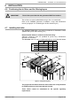
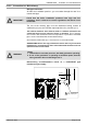
In accordance with the diagram, it is imperative to fi t the boiler and its
installation with the following components:
• powered isolating valve (with an end of run contact*) on the fl ow tapping
on each generator's main exchanger,
• balancing / isolating valve on each generator's return tapping,
• anti-return fl ap,
• fi lters,
• mud cup,
• expansion vessel,
• effective drain mechanism,
• safety valve set at 6 bars, on each generator, sized according to each
generator's heat output (see location fi gure 1 page 8).
• disconnector on the boiler's fi lling circuit in relation to the supply network.
(*) The end of run contact only allows the generator to start up when full
opening is reached.
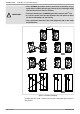
The VARMAX TWIN are delivered either in 2/3 tapping connection
version or in 4 tapping connection version. A 2/3 tapping version cannot
be converted into a 4 tapping version and vice versa.
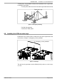
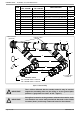
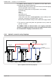
4.16.1. Hydraulic connection using 2 tappings
fi gure 9 - Hydraulic connection using 2 tappings
B3000
B3000
QAZ36
(fournie)
OCI345
(fourni)
OCI345
(fourni)
câble «bus LPB»
(fourni)
Main exchanger
output
(hot return fl ange blocked)
Cold return
LPB bus cable
(supplied)
QAZ36
(supplied)
OCI345
(supplied)
OCI345
(supplied)