
Operating Instructions and Installation Instructions

Page 28 / 56 00BNO9132-#
VARMAX TWIN - Installation, Use and Maintenance
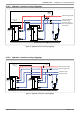
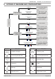
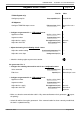
L NY1 NY2L NL NL N
QX2 QX3 QX1 AUX2 AUX1
230 VAC 50 Hz
power supply
}
}
Alarm
relay
DB MB
}
Isolating
valve Q1.2
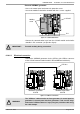
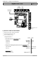
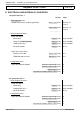
D. SPECIFIC START-UP PROCEDURE
Make the accessories' electrical connections.
Start up the generator on its own.
Make the following settings:
On generator No. 1
Line No. Value
• Set the date and time: Time and date menu
Set the time
Hour / minute (1) HH.MM
Set the date
Day / month (2) DD.MM
Set the year
Year (3) YYYY
• Confi gure the isolating valve and its end of run: Confi guration menu
Valve command
Relay output QX3 (5892) K37 exhaust fl ap
End of run
Input H5 (5977) Exhaust fl ap info
return
• Confi guration menu
Start up heating circuit 1
Heating circuit 1 (5710) Start
LPB bus
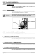
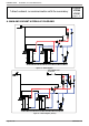
Diagrams: VX200 / VX201
page 3 / 6
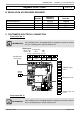
BX2
Gnd
BX3
Gnd
B3
Gnd
B9
Gnd
H1
Gnd
H5
Gnd
}
Isolating valve end
of run