
Operating Instructions and Installation Instructions

Edition: 02 / 2015 Page 29 / 56
VARMAX TWIN - Installation, Use and Maintenance
Line No. Value
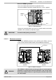
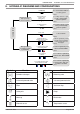
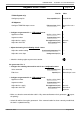
VX200 diagram only:
Confi gure pump Q2
Relay output QX2 (5891) Pump CC1 Q2
All diagrams:
Confi gure TWIN B10 output sensor
BX2 sensor input (5931) Common fl ow sensor
B10
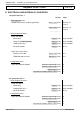
• Confi gure as generator No. 1: LPB network menu
Appliance number
Appliance address (6600) 1
Segment number
Segment address (6601) 0
Adjust the bus supply
Bus supply function (6604) Automatic
Adjust the clock rate
Clock operation (6640) Master
• Adjust the heating circuit Heating circuit 1 menu
Adjust the comfort setting
Comfort setting temperature (710) - - -
Adjust the curve slope
Heating curve slope (720) - - -
• Switch the heating regime to permanent comfort
On generator No. 2
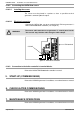
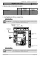
• Confi gure the isolating valve and its end of run: Confi guration menu
Valve command
Relay output QX3 (5892) K37 exhaust fl ap
End of run
Input H5 (5977) Exhaust fl ap info return
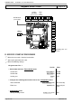
• Confi gure as generator No. 2: LPB network menu
Appliance number
Appliance address (6600) 2
Segment number
Segment address (6601) 0
Adjust the bus supply
Bus supply function (6604) Automatic
Adjust the clock rate
Clock operation (6640) Slave without
adjustment
• Make sure that the communication cable is fully connected between the 2 generators (
!
respect
the polarity).
• Switch off and back on again generator 2. If the communication has been correctly established,
the clock is updated correctly.
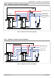
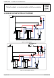
Diagrams: VX200 / VX201
page 4 / 6