
Operating Instructions and Installation Instructions

Page 30 / 56 00BNO9132-#
VARMAX TWIN - Installation, Use and Maintenance
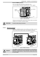
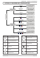
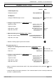
• Inputs/outputs test menu
Check the outputs
Alarm relay
Relay test (7700) Relay output QX1
Pump Q2 (VX200 diagram)
Relay test (7700) Relay output QX2
Isolating valve Q1.1
Relay test (7700) Relay output QX3
Reset the outputs
Relay test (7700) No test
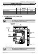
Check the sensor values
External sensor B9
External T° B9 (7730) in °C
TWIN B10 output sensor
BX2 sensor T° (7821) in °C
• Confi guration menu
Check the hydraulic diagram
Generator 1 inspection No. (6212) 14
Generator 2 inspection No. (6213) 0
DHW information (6215) 0
Information about heating circuits 3, 2 and 1 (6217) 1
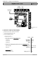
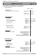
On generator No. 2
• Inputs/outputs test menu
Check the outputs
Alarm relay
Relay test (7700) Relay output QX1
Isolating valve Q1.2
Relay test (7700) Relay output QX3
Reset the outputs
Relay test (7700) No test
• Confi guration menu
Check the hydraulic diagram
Generator 1 inspection No. (6212) 14
Generator 2 inspection No. (6213) 0
DHW information (6215) 0
Information about heating circuits 3, 2 and 1 (6217) 0
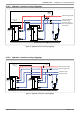
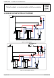
Diagrams: VX200 / VX201
page 5 / 6
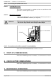
E. ELECTRICAL AND HYDRAULIC VALIDATION
On generator No. 1
Line No. Value
• Flow diagnostic menu
Validate the presence of all the generators
Gener 1 status (8100) Released / not
released
Gener 2 status (8101) Released / not
released
...............................