
Operating Instructions and Installation Instructions

Page 36 / 56 00BNO9132-#
VARMAX TWIN - Installation, Use and Maintenance
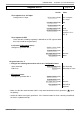
For a request via 0...10V input
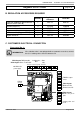
• Inputs/outputs test menu
Voltage in H1
H1 voltage signal (7840) To be validated with
the voltage sent by
the boiler room's
PLC
For a request via LPB
If the boiler room's regulator is confi gured
as slave clock, it must retrieve the date
and time.
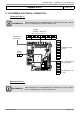
• Inputs/outputs test menu
Check the outputs
Alarm relay
Relay test (7700) Relay output QX1
Isolating valve Q1.1
Relay test (7700) Relay output QX3
Reset the outputs
Relay test (7700) No test
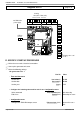
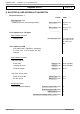
Check the sensor values
External sensor B9
External T° B9 (7730) in °C
B1 fl ow sensor
BX2 sensor T° (7821) in °C
• Confi guration menu
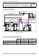
Check the hydraulic diagram
Generator 1 inspection No. (6212) 14
Generator 2 inspection No. (6213) 0
DHW information (6215) 0
Information about heating circuits 3, 2 and 1 (6217) 0
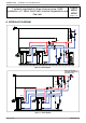
Diagram: VX211
page 5 / 6
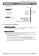
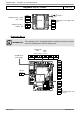
E. ELECTRICAL AND HYDRAULIC VALIDATION
On generator No. 1
Line No. Value
• Flow diagnostic menu
Validate the presence of all the generators
Gener 1 status (8100) Released / not
released
Gener 2 status (8101) Released / not
released
...............................