
Operating Instructions and Installation Instructions


Page 4 / 56 00BNO9132-#
VARMAX TWIN - Installation, Use and Maintenance
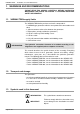
1. WARNINGS AND RECOMMENDATIONS
PLEASE READ THIS MANUAL CAREFULLY BEFORE INSTALLING,
MAINTAINING AND USING THE BOILER. IT CONTAINS IMPORTANT
SAFETY INFORMATION.
1.1. VARMAX TWIN supply limits
The VARMAX TWIN boiler you have received is composed of:
• 2 VARMAX type generators with the same power to be connected to each
other
• 1 450 mm common exhaust fl ue between the generators
• 4 Tefl on plates (to help position the generators)
• 2 LPB bus cable trays with holding screws
• 1 LPB bus cable
• 2 OCI 345 communication modules with holding screws
• 1 QAZ 36 fl ow sensor
This manual describes the specifi c features of the assembly. Everything
which relates to one of the 2 generators (internal accessibility, settings,
maintenance, spare parts, etc.) is described in the particular generator's
manual. The following data must therefore be used:
- For the VARMAX TWIN 550, see the information for the VARMAX 275,
- For the VARMAX TWIN 640, see the information for the VARMAX 320,
- For the VARMAX TWIN 780, see the information for the VARMAX 390,
- For the VARMAX TWIN 900, see the information for the VARMAX 450.
1.2. Transport and storage
The generators:
- must be arranged horizontally in a place where the temperature is between
0 °C and +50 °C and whose relative humidity is between 5% and 95%.
- must not be stacked,
- must be protected from humidity.
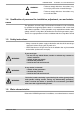
1.3. Symbols used in this document
INFORMATION: This symbol draws attention to comments.
!
IMPORTANT:
Failure to comply with these instructions may
cause damage to the installation or to other
objects.
INFORMATION:
The hydraulic connection elements to be added according to the
diagram are not supplied (refer to chapters 4.12 and 8).