
Operating Instructions and Installation Instructions

Page 40 / 56 00BNO9132-#
VARMAX TWIN - Installation, Use and Maintenance
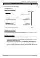
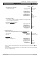
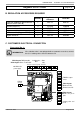
Generator No. 2:
INFORMATION:
If the isolation valve is not equipped with an automatic reset valve, connect
the Q1.2 isolating valve's closure contact to Y2.
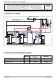
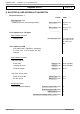
Diagrams: VX210 / VX220
page 3 / 8
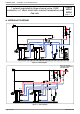
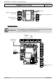
L NY1 NY2L NL NL N
QX2 QX3 QX1 AUX2 AUX1
230 VAC 50 Hz
power supply
}
DB MB
}
Isolating valve
Q1.2
LPB bus
}
Alarm
relay
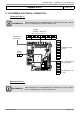
AVS75
QX21
No.
QX22
No.
QX23
BX21
Gnd
BX22
Gnd
H2
Gnd
}
}
}
}
Module 1
Regulated circuit output sensor
B1
Heating circuit No. 1 mixer
valve Y1/Y2
Heating circuit No. 1
circulator Q2
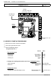
BX2
Gnd
BX3
Gnd
B3
Gnd
B9
Gnd
H1
Gnd
H5
Gnd
}
Isolating valve end
of run