
Operating Instructions and Installation Instructions


Edition: 02 / 2015 Page 41 / 56
VARMAX TWIN - Installation, Use and Maintenance
!
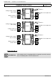
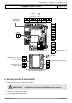
IMPORTANT: Confi gure the switches on the AVS75 extension module.
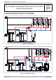
Diagrams: VX210 / VX220
page 4 / 8
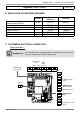
D. SPECIFIC START-UP PROCEDURE
Make the accessories' electrical connections.
Start up the generator on its own.
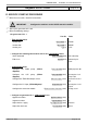
Make the following settings:
On generator No. 1
Line No. Value
• Time and date menu
Set the time
Hour / minute (1) HH.MM
Set the date
Day / month (2) DD.MM
Set the year
Year (3) YYYY
• Confi gure the isolating valve and its end of run: Confi guration menu
Valve command
Relay output QX3 (5892) K37 exhaust fl ap
End of run
Input H5 (5977) Exhaust fl ap info
return
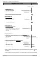
• Confi guration menu
Confi gure the DHW pump (VX210
diagram)
Relay output QX2 (5891) DHW pump/valve Q3
Confi gure the Q15 pump (VX220
diagram)
Relay output QX2 (5891) Consumption circuit
pump 1 Q15
Confi gure the TWIN B10 output sensor
BX2 sensor input (5931) Common fl ow sensor
B10
Confi gure the H1 input (VX220 diagram)
H1 input function (5977) Consumption circuit 1
request
Confi gure the extension module
Extension module 1 function 1 (6020) Heating circuit 1
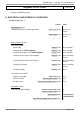
• Confi gure as generator No. 1: LPB network menu
Appliance number
Appliance address (6600) 1
Segment number
Segment address (6601) 0
Adjust the bus supply
Bus supply function (6604) Automatic
Adjust the clock rate
Clock operation (6640) Master