
Operating Instructions and Installation Instructions


Page 48 / 56 00BNO9132-#
VARMAX TWIN - Installation, Use and Maintenance
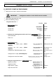
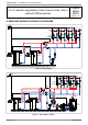
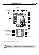
AVS75
QX21
No.
QX22
No.
QX23
BX21
Gnd
BX22
Gnd
H2
Gnd
}
}
}
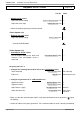
AVS75
QX21
No.
QX22
No.
QX23
BX21
Gnd
BX22
Gnd
H2
Gnd
}
}
}
AVS75
QX21
No.
QX22
No.
QX23
BX21
Gnd
BX22
Gnd
H2
Gnd
}
}
}
}
}
}
Module 1
Module 2
Module 3
Regulated circuit output sensor
B1
Regulated circuit output sensor
B12
Regulated circuit output sensor
B14
Heating circuit No. 1 mixer
valve Y1/Y2
Heating circuit No. 2 mixer
valve Y5/Y6
Heating circuit No. 3 mixer
valve Y11/Y12
Heating circuit No. 1
circulator Q2
Heating circuit No. 2
circulator Q6
Heating circuit No. 3
circulator Q20
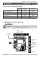
Diagrams: VX202 / VX212
page 3 / 9
Generator No. 2:
INFORMATION:
If the isolation valve is not equipped with an automatic reset valve, connect
the Q1.2 isolating valve's closure contact to Y2.