
Operating Instructions and Installation Instructions


Page 50 / 56 00BNO9132-#
VARMAX TWIN - Installation, Use and Maintenance
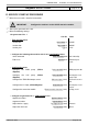
On generator No. 1
Line No. Value
• Time and date menu
Set the time
Hour / minute (1) HH.MM
Set the date
Day / month (2) DD.MM
Set the year
Year (3) YYYY
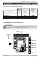
• Confi gure the isolating valve and its end of run: Confi guration menu
Valve command
Relay output QX3 (5892) K37 exhaust fl ap
End of run
Input H5 (5977) Exhaust fl ap info return
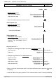
• Confi guration menu
Start up heating circuit 1
Heating circuit 2 (5710) Start
Start up heating circuit 2
Heating circuit 2 (5715) Start
Start up heating circuit 3
Heating circuit 3 (5721) Start
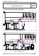
VX212 diagram only:
Defi ne a low heel H1 input function (5950) Consumption circuit 1
request .
Position a shunt on H1 OR reverse the
contact direction
Contact type (5951) Normally-closed
contact (NC)
For the DHW to be effective, an
activator must be defi ned, even if it is
not connected
Relay output QX2 (5891) DHW pump/valve Q3
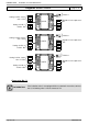
Confi gure pump Q1
Relay output QX3 (5892) Boiler pump Q1
Confi gure TWIN B10 output sensor
BX2 sensor input (5931) Common fl ow sensor
B10
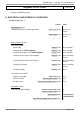
Confi gure the extension modules
Extension module 1 function 1 (6020) Heating circuit 1
Extension module 2 function 1 (6021) Heating circuit 2
Extension module 3 function 1 (6022) Heating circuit 3
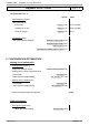
• Confi gure as generator No. 1: LPB network menu
Appliance number
Appliance address (6600) 1
Segment number
Segment address (6601) 0
Adjust the bus supply
Bus supply function (6604) Automatic
Adjust the clock rate
Clock operation (6640) Master
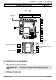
Diagrams: VX202 / VX212
page 5 / 9